Rotary carrying manipulator

A technology of manipulators and rotary joints, applied in the field of robots, can solve the problems of low efficiency of handling manipulators, achieve the effects of saving handling time, improving automation level, and improving production efficiency

Inactive Publication Date: 2017-05-10
SHANGHAI DIANJI UNIV
View PDF8 Cites 21 Cited by
  • Summary
  • Abstract
  • Description
  • Claims
  • Application Information

AI Technical Summary

Problems solved by technology

[0005] The purpose of the present invention is to solve the problem of low efficiency of the common handling manipulator at present, and propose a rotating handling manip

Method used


Image

  • Rotary carrying manipulator
  • Rotary carrying manipulator

Examples


Embodiment Construction

[0025] In order to make the technical means, creative features, goals and effects achieved by the present invention easy to understand, the present invention will be further elaborated below in conjunction with illustrations and specific embodiments.

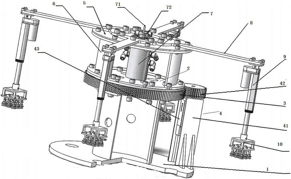
[0026] Such as figure 1 As shown, a kind of rotary handling manipulator proposed by the present invention includes

[0027] A base 1, an annular slewing support connected to the base 1, the slewing support includes two parts, the slewing support inner ring 2 and the slewing support outer ring 3, the slewing support outer ring 3 has a tooth-like structure;

[0028] One side of the base 1 is provided with a driving device 4, the driving device 4 includes a motor bracket 41 arranged on the upper end of the base 1, the inside of the motor bracket 41 is provided with a driving motor 43, and the output shaft end of the driving motor is connected to There is a driving gear 42, and the driving gear 42 meshes with the slewing support ou...


PUM


Abstract

The invention provides a rotary carrying manipulator. The rotary carrying manipulator comprises a base and an annular rotary support connected with the base, wherein the rotary support comprises a rotary support inner ring and a rotary support outer ring, and the rotary support outer ring is of a dentate structure; a drive device is arranged on one side of the base and comprises a motor bracket arranged at the upper end of the base, a drive motor is arranged in the motor bracket, and the output shaft end of the drive motor is connected with a drive gear meshed with the rotary support outer ring; and an upper cover plate is arranged at the upper end of the rotary support outer ring and connected with the rotary support outer ring through an upper support column, a through hole is formed in the middle part of the upper cover plate, a pneumatic/electric rotating joint is mounted at the lower end of the through hole, four support arms are evenly distributed on the 360-degree circumference of the upper cover plate, one end of each support arm is fastened to the upper end of the upper cover plate through a bolt, an electric push rod is mounted below the other end of each support arm, and a vacuum cup array is mounted at an extending end of each electric push rod.

Description

technical field [0001] The invention relates to the technical field of robots, in particular to a rotary transfer manipulator with a rotary end effector. Background technique [0002] The rotary handling manipulator is a general-purpose mechanical equipment, mainly used to complete the handling of workpieces between two fixed stations. At present, in the automatic production line, it is very common to use manipulators to transport workpieces. The common manipulators on the production line are mainly manipulators with a series structure. This kind of manipulator technology is mature and reliable. Repeatedly move back and forth along the same trajectory, so the efficiency of handling workpieces is affected to a certain extent. For some relatively large handling occasions, it will affect the production efficiency of the entire production line, and ultimately affect the economic benefits of the enterprise. [0003] At present, the more common handling manipulators on the produ...

Claims


Application Information

Patent Timeline
IPC IPC(8): B65G47/91B25J9/00
CPCB65G47/918B25J9/00B65G47/915B65G47/917
Inventor 唐国明
Owner SHANGHAI DIANJI UNIV
Why Eureka
Try Eureka