Receiver

A technology of material receiving device and hopper, which is applied in the directions of manual conveying device, transportation and packaging, loading/unloading, etc. It can solve problems such as troublesome transportation, affecting work efficiency, and inability to discharge materials from the material port, so as to reduce handling time, The effect of improving work efficiency and simple structure

Inactive Publication Date: 2013-12-11
戴启彬
View PDF8 Cites 5 Cited by
  • Summary
  • Abstract
  • Description
  • Claims
  • Application Information

AI Technical Summary

Problems solved by technology

[0002] The existing material receiving trough is generally used for receiving materials at the material outlet. When the material receiving trough is full of materials, it needs to be replaced.

Method used

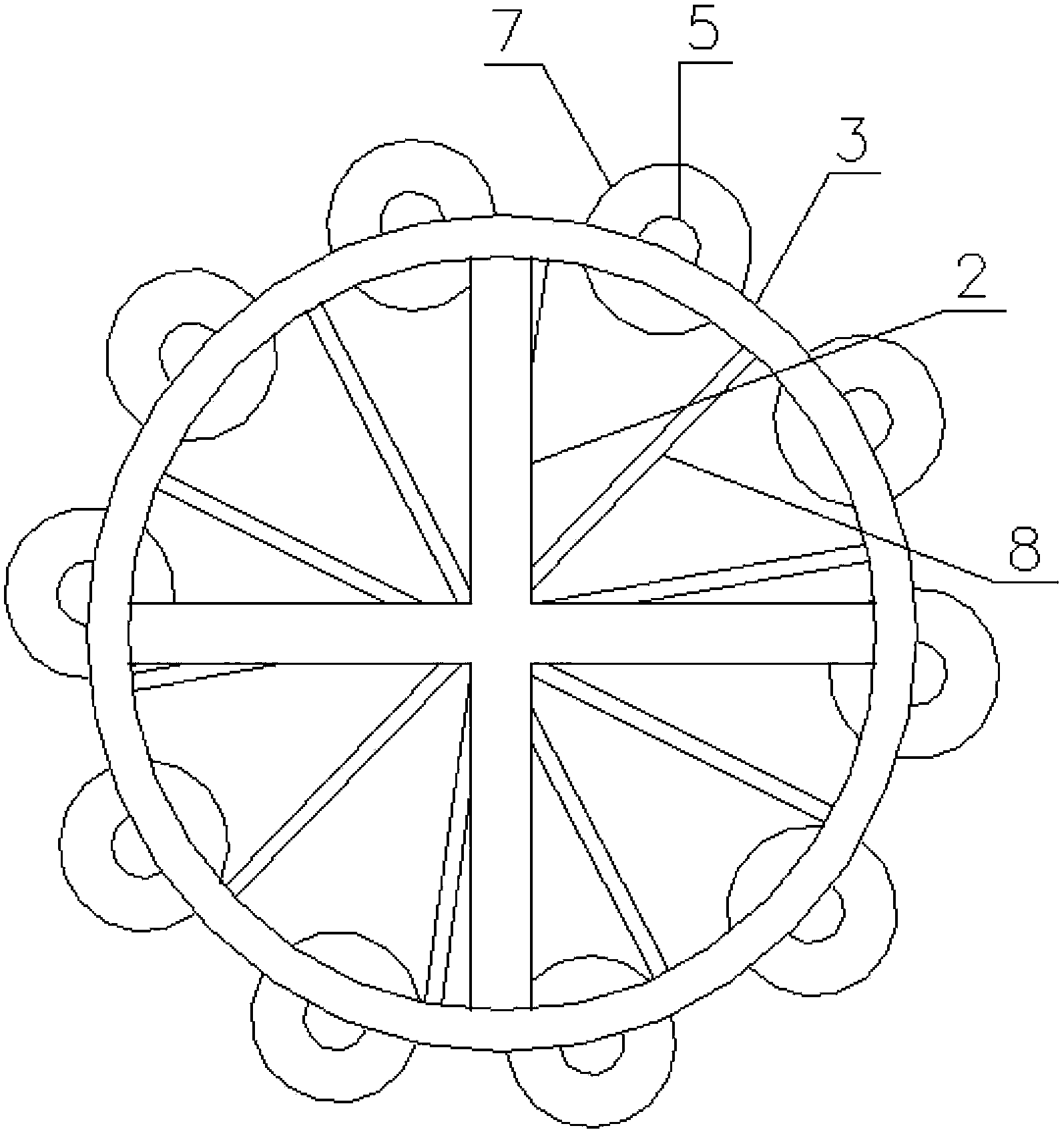
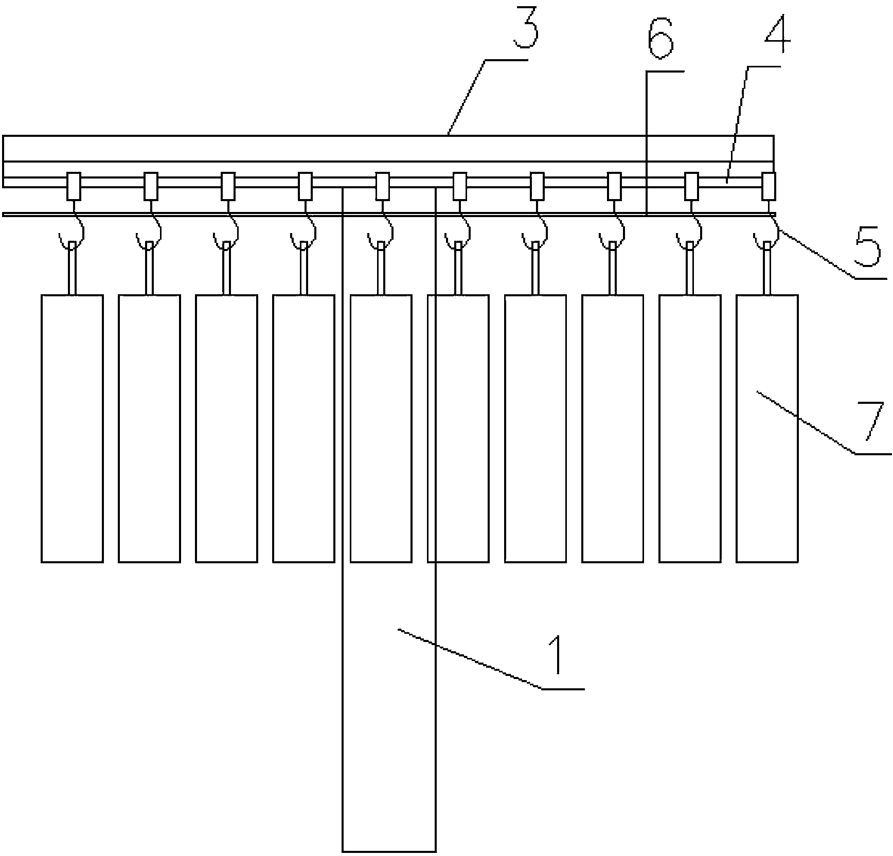

Image

  • Receiver
  • Receiver

Examples


Embodiment Construction

[0012] In order to make the technical means, creative features, goals and effects achieved by the present invention easy to understand, the present invention will be further described below in conjunction with specific illustrations.

[0013] Such as figure 1 and figure 2 A kind of material receiving device shown, comprises support 1, and support 1 is provided with horizontal fixing rod 2, and horizontal fixing rod 2 is provided with ring frame 3, and ring frame 3 is provided with chute 4, and inside chute 4 A hook 5 is provided for sliding, and a rope 6 is strung on the hook 5. The rope 6 is a steel wire rope. 8. The connecting rod 8 is supported on the rope 6 between the 5 linked hooks.

[0014] The basic principles, main features and advantages of the present invention have been shown and described above. Those skilled in the industry should understand that the present invention is not limited by the above-mentioned embodiments. What are described in the above-mentioned...


PUM


Abstract

A receiver, which relates to an auxiliary material device, comprises a support, horizontal fixed rods are arranged on the support, a ring frame is arranged on the horizontal fixed rods, a slide way is arranged in the ring frame, hooks are slidably arranged in the slide way, and are strung by a rope, the rope is knotted at both sides of each hook, and receiving hoppers are arranged on the lower ends of the hooks. The structure of the receiver is simple, the design is reasonable, the rope can be utilized to pull the hooks to slide to and fro on the ring to control the receiving hoppers to move, and the receiver is convenient and efficient, shortens the handling time, saves time and labor, and increases working efficiency.

Description

Technical field: [0001] The invention relates to a material receiving device. Background technique: [0002] The existing material receiving trough is generally used for receiving materials at the material outlet. When the material receiving trough is full of materials, it needs to be replaced. Invention content: [0003] The technical problem to be solved by the present invention is to overcome the defects of the prior art and provide a material receiving device for quickly replacing the material receiving tank. [0004] The technical problem to be solved by the present invention is realized by the following technical solutions. [0005] A material receiving device, characterized in that it includes a bracket, a horizontal fixing rod is arranged on the bracket, a ring frame is arranged on the horizontal fixing rod, a chute is arranged in the ring frame, a hook is slid in the chute, and a hook is mounted on the hook. There are ropes on the string, the ropes at both ends ...

Claims


Application Information

Patent Timeline
Patent Type & Authority Applications(China)
IPC IPC(8): B65G9/00B65G69/00
Inventor 戴启彬
Owner 戴启彬
Why Eureka
Try Eureka