Damping Forced Positioning Mechanism of Furniture Turning Device

A technology of turning device and positioning mechanism, which is applied in the direction of building construction, switches with braking devices, door/window accessories, etc. It can solve the problem that the buffer damping force does not have the adjustment function, cannot meet the needs of use, and cannot achieve uniformity, etc. problems, to achieve the effect of small collision, stable work and long service life

Active Publication Date: 2017-12-15
伍志勇
View PDF6 Cites 0 Cited by
  • Summary
  • Abstract
  • Description
  • Claims
  • Application Information

AI Technical Summary

Problems solved by technology

It is said that this structure can reduce noise, and the closing or opening movement of the cabinet door is more flexible. During the movement of the cabinet door, the overall translational movement can avoid the situation that ordinary cabinet doors may hit the head; however, the upper The flap hinge only achieves cushioning and damping through the elastic component, and the force during the closing or opening movement cannot achieve a uniform effect, and the elastic component has a large friction force and high noise when the upper flap is hinged to open and close, and it is not easy to use in the actual use process. Displacement is easy to appear in the center, resulting in the failure of the buffer damping. At the same time, the buffer damping force does not have the adjustment function, which cannot meet the needs of users.

Method used


Image

  • Damping Forced Positioning Mechanism of Furniture Turning Device
  • Damping Forced Positioning Mechanism of Furniture Turning Device
  • Damping Forced Positioning Mechanism of Furniture Turning Device

Examples


no. 1 example

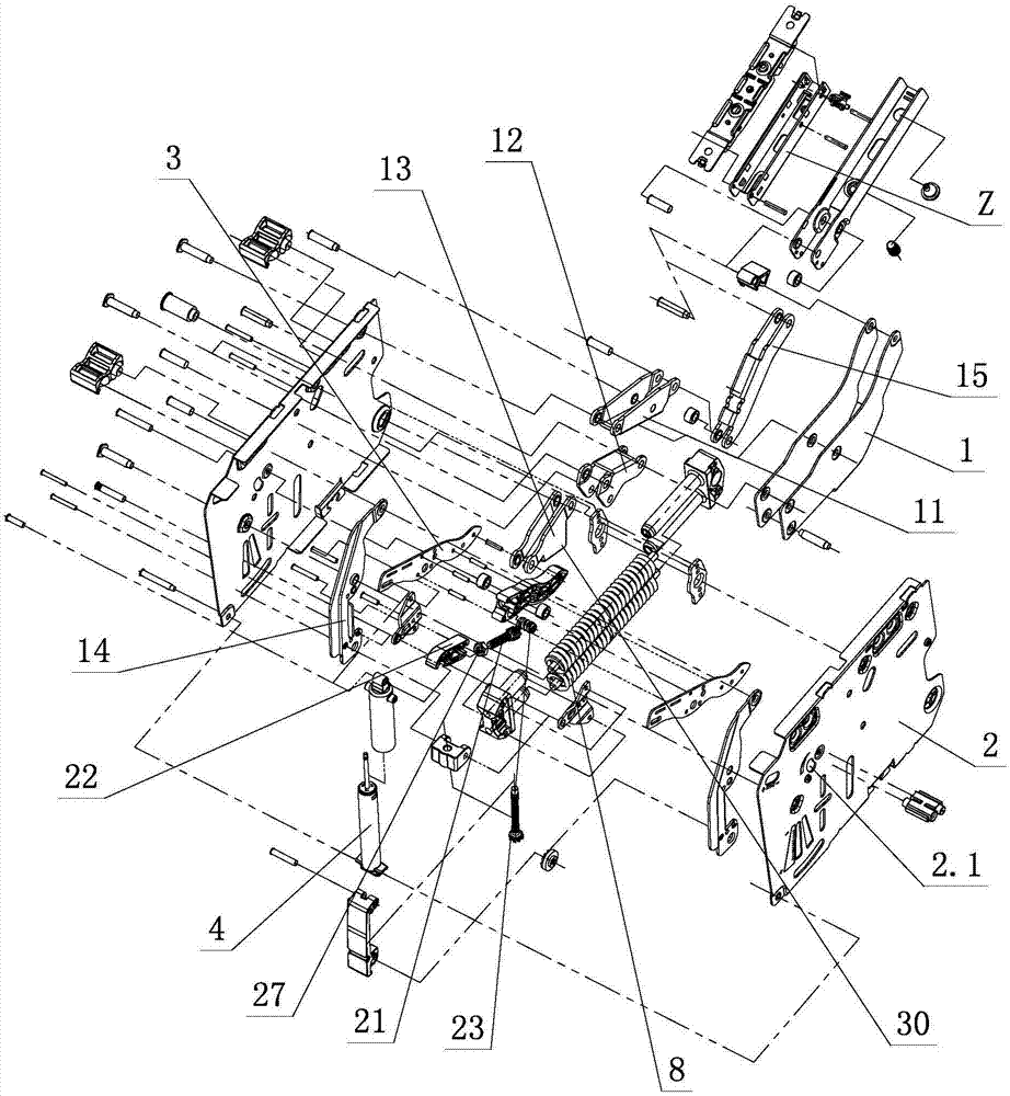
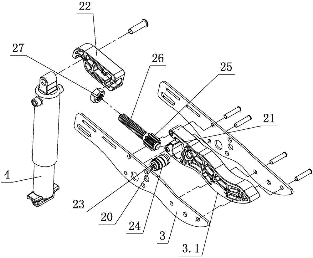
[0030] see Figure 1-Figure 6 , the damping forced positioning mechanism of the furniture overturning device includes a push element 1, a connecting arm assembly and a fixed element 2, the push element 1 is hinged to the fixed element 2 through the connecting arm assembly, an elastic assembly is arranged on the fixed element 2, and the push element 1 The elastic component is elastically flipped open and closed on the fixed element 2, and also includes a lever element 3 and a damper 4. The lever element 3 is rotatably arranged on the fixed element 2, and one end interacts with the damper 4, and the other end is at least on the push element 1. It interacts with the pushing element 1 when flipping and closing a stroke; the connecting arm assembly is provided with a connecting arm positioning part 30 .

[0031] When the push element 1 is flipped and closed relative to the fixed element 2 for at least a certain stroke, the end of the lever element 3 is in contact with the push elem...

no. 2 example

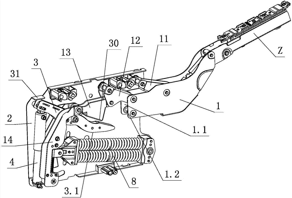
[0047] see Figure 7-Figure 10 , the damping forced positioning mechanism of the furniture turning device is different from the first embodiment in that the connecting arm assembly at least includes a first connecting arm 11, a second connecting arm 12 and a third connecting arm 13, and the first connecting arm 11 The second connecting arm 12 is hinged with the pushing element 1, the fixing element 2 and the third connecting arm 13 respectively; the second connecting arm 12 is provided with a connecting arm locator 33, and the connecting arm is positioned One end of piece 33 is rotatably arranged on the fixed element 2, the middle part is slidably arranged on the second connecting arm 12, and is interlocked with the second connecting arm 12. There is a fixed positioning part 31 on it; when the idle section of the lever element 3 and the action part 1.2 of the push element 1 are in the initial contact state, the connecting arm positioning part 30 and the fixed positioning part ...


PUM


Abstract

The invention discloses a damping forced positioning mechanism of a furniture turnover device. The damping forced positioning mechanism comprises a push element, a connecting arm assembly and a fixed element, wherein the push element is articulated with the fixed element via the connecting arm assembly, an elastic assembly is arranged on the fixed element, and the push element is opened and closed on the fixed element in an elastic turnover manner via the elastic assembly. The damping forced positioning mechanism further comprises a lever element and a damper, wherein the lever element is arranged on the fixed element in a rotatable manner, one end of the lever element interacts with the damper, the other end of the lever element interacts with the push element at least when the push element is turned over and closed a stroke, the connecting arm assembly and the fixed element are respectively provided with a connecting arm positioning portion and a fixed positioning portion, and when the lever element is connected with the push element first time, the lever element is positioned on the fixed element under the coordination of the connecting arm positioning portion and the fixed positioning portion. The damping forced positioning mechanism has strong practicability via the improved structure.

Description

technical field [0001] The invention relates to a damping forced positioning mechanism of a furniture overturning device. Background technique [0002] The Chinese patent document number is CN202039710U, which discloses a hinge on November 16, 2011. The curved end of the first rotating arm of this structure is rotatably connected to the base plate, and the curved end of the second rotating arm is rotatably connected to the base plate. The two ends of the above-mentioned connecting arms that can overlap with the respective straight ends of the first rotating arm and the second rotating arm at the same time are rotatably connected with the respective straight ends of the first rotating arm and the second rotating arm respectively, and the connecting arms are located at the first Between the rotating arm and the second rotating arm, the bent end of the first rotating arm is hinged with the free end of the movable rod of the gas rod, and the fixed rod of the gas rod can be movab...

Claims


Application Information

Patent Timeline
Patent Type & Authority Patents(China)
IPC IPC(8): E05F3/20E05F1/12
CPCE05F1/12E05F3/20E05Y2900/20
Inventor 伍志勇
Owner 伍志勇
Why Eureka
Try Eureka