
Hydraulically driven reducer release device

A technology of disengagement device and reducer, which is applied to fluid-driven clutches, non-mechanical-driven clutches, mechanical equipment, etc., can solve the problems of long time, high risk, and high installation errors, and achieve the effect of avoiding tedious work.

Active Publication Date: 2019-09-03
BOSCH REXROTH BEIJING HYDRAULIC
View PDF12 Cites 0 Cited by
  • Summary
  • Abstract
  • Description
  • Claims
  • Application Information

AI Technical Summary

Problems solved by technology

Therefore, the manual disengagement device requires manual disassembly and assembly of the end cover of the reducer, repeated disassembly and assembly of the gear shaft, and repeated addition and discharge of gear oil. The duplication of the process is cumbersome and messy, and the possibility of incorrect installation or installation errors is high.
In addition, due to repeated filling and discharging of gear oil, there is a high risk of adding oil mixed with impurities to the inner cavity of the reducer, and gear oil may leak due to repeated removal of end caps
[0005] When it is necessary to move the machine to transition, because the above work needs to be done manually, it takes a long time and the efficiency is low

Method used


Image

  • Hydraulically driven reducer release device
  • Hydraulically driven reducer release device
  • Hydraulically driven reducer release device

Examples


Embodiment Construction

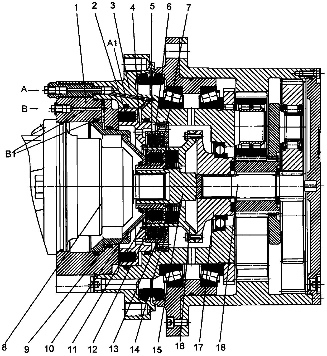
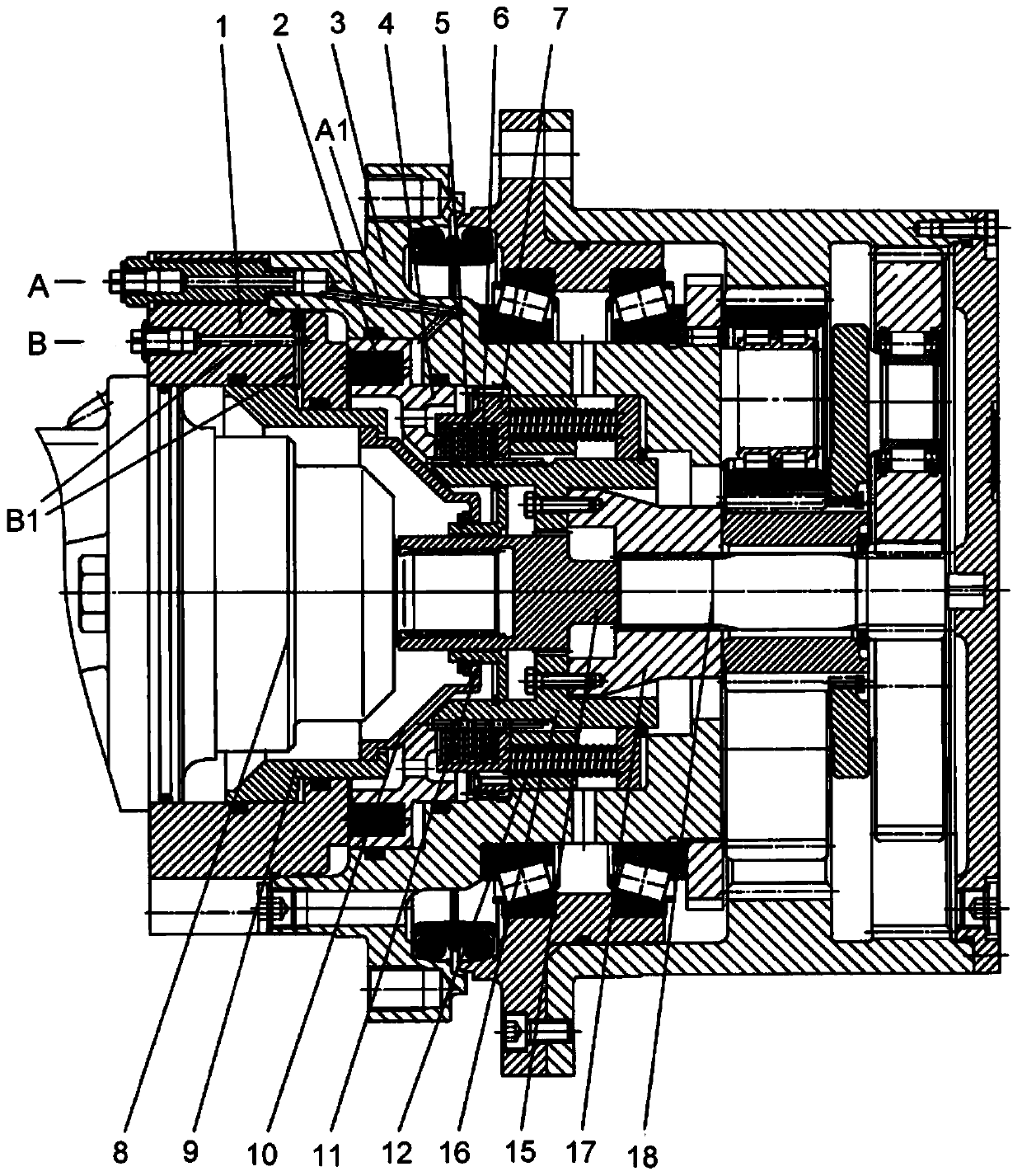
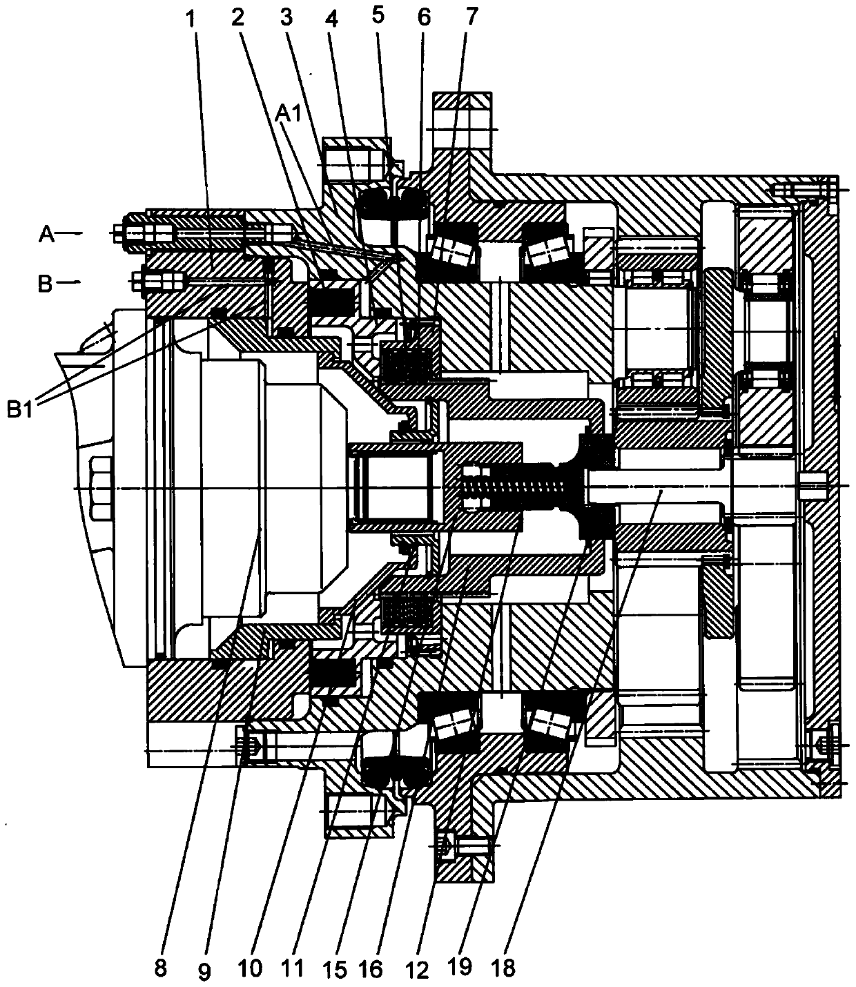
[0024] The invention mainly relates to a hydraulically driven reducer release device, in particular to a reducer release device for walking machinery.

[0025] The hydraulically driven speed reducer disengaging device according to the present invention will be described in detail below with reference to the accompanying drawings. Throughout the drawings, structurally or functionally identical or similar elements are denoted by the same reference numerals.

[0026] Figure 1 to Figure 3 Three hydraulically driven reducer disengagement devices according to the present invention are shown.

[0027] refer to Figure 1 to Figure 3 , shows the motor housing 1, the motor 8 and the main shaft 3, the motor housing 1, the motor 8 are connected with the main shaft 3 by screws (not shown), and the main shaft 3 is fixed to a fixed frame (not shown). figure 1 Also shown is the drive shaft 15 connected to the output shaft of the motor, and the central gear shaft 18 of the reducer. In the ...


PUM


Abstract

The invention discloses a hydraulically driven type speed reducer disconnection device. The hydraulically driven type speed reducer disconnection device comprises a fixed braking shell, a fluid port for braking and a fluid port for disconnection. By selectively supplying fluid to one or both of the fluid port for braking and the fluid port for disconnection, one or both of a motor output shaft of a driving speed reducer and a speed reducer input shaft is / are selectively connected or disconnected with the fixed braking shell, so that the speed reducer input shaft is in the first working state that the input shaft is driven by the motor output shaft, specifically, the motor output shaft is disconnected with the braking shell but connected with the speed reducer input shaft, or the speed reducer input shaft is in the second disconnected state that the input shaft is disconnected with the motor output shaft, specifically, the motor output shaft is disconnected with the speed reducer input shaft, or the speed reducer input shaft is in the third braked state that the motor output shaft is connected with the braking shell as well as the speed reducer input shaft.

Description

technical field [0001] The invention relates to a hydraulically driven reducer release device, in particular to a reducer release device for walking machinery. Background technique [0002] A mobile machine for outdoor work is generally equipped with a drive motor and a reducer connected to the drive motor. The reducer reduces the output speed of the output shaft of the drive motor and increases the output torque of the output shaft to be transmitted to the tires of the mobile machine. [0003] A decelerator release device is arranged between the driving motor and the decelerator. The disengagement device of the reducer enables the input shaft of the reducer to be selectively placed in the first working state driven by the output shaft of the motor, or in the second disengaged state disengaged from the output shaft of the motor, or in the third braked state. The moving state, so that the mobile machinery is placed in the normal working state or disengaged state or braking s...

Claims


Application Information

Patent Timeline
Patent Type & Authority Patents(China)
IPC IPC(8): F16D25/063
Inventor 张尧
Owner BOSCH REXROTH BEIJING HYDRAULIC
Learn More