LED backlight light bar and application thereof

A technology of LED backlight and backlight, which is applied in the field of optical devices, can solve the problems of waste of materials and unsightly appearance, and achieve the effect of material saving and beautiful products

Pending Publication Date: 2017-05-10
SHINEON BEIJING TECH
View PDF6 Cites 0 Cited by
  • Summary
  • Abstract
  • Description
  • Claims
  • Application Information

AI Technical Summary

Problems solved by technology

[0002] At present, the LED backlight strips commonly used in display devices and panel lights are mainly assembled with a plurality of light-emitting units 2 on a strip substrate 1 (see figu

Method used


Image

  • LED backlight light bar and application thereof
  • LED backlight light bar and application thereof
  • LED backlight light bar and application thereof

Examples


Embodiment 1

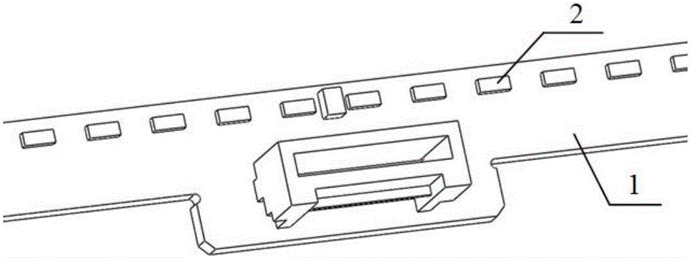
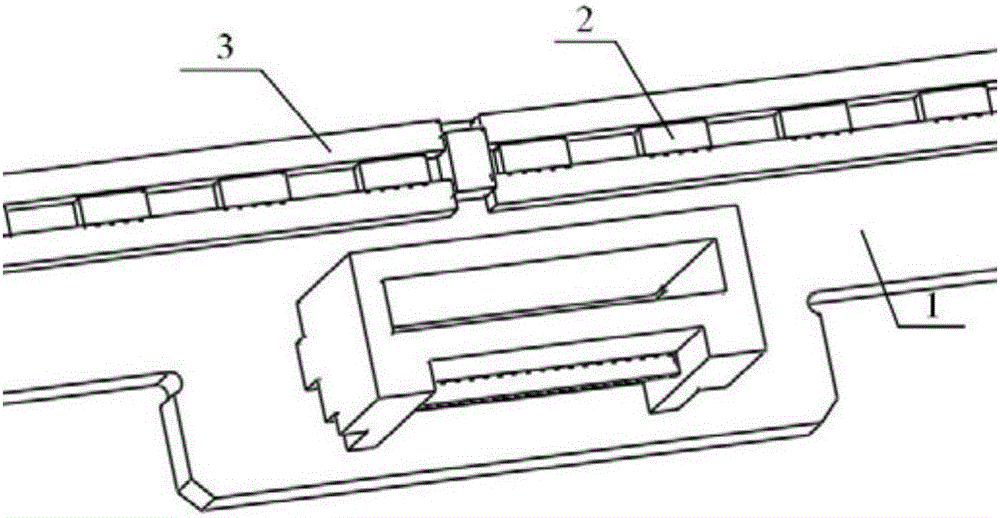
[0019] Such as figure 2 As shown, the present invention provides an LED backlight strip, which at least includes: a substrate 1, a light-emitting unit 2, and a light-shielding strip 3; The unit 2 is assembled in the U-shaped groove formed by the two shading strips 3 and the base plate 1 .

[0020] Preferably, the luminous groove surface of the U-shaped groove can be adjusted by adjusting the distance between the two light-shielding strips 3 .

[0021] Preferably, the light emitting unit 2 is an LED lamp bead.

[0022] Preferably, the shading strip 3 is bonded on the substrate 1 by means of double-sided adhesive or natural colloid curing.

[0023] In the LED backlight strip provided in this embodiment, since the light-emitting unit 2 is placed in the U-shaped groove formed by the two light-shielding strips 3 and the substrate 1, the arbitrary adjustment of the light-emitting groove surface of the backlight light strip is realized. Realize the ultra-narrow frame of liquid cr...

Embodiment 2

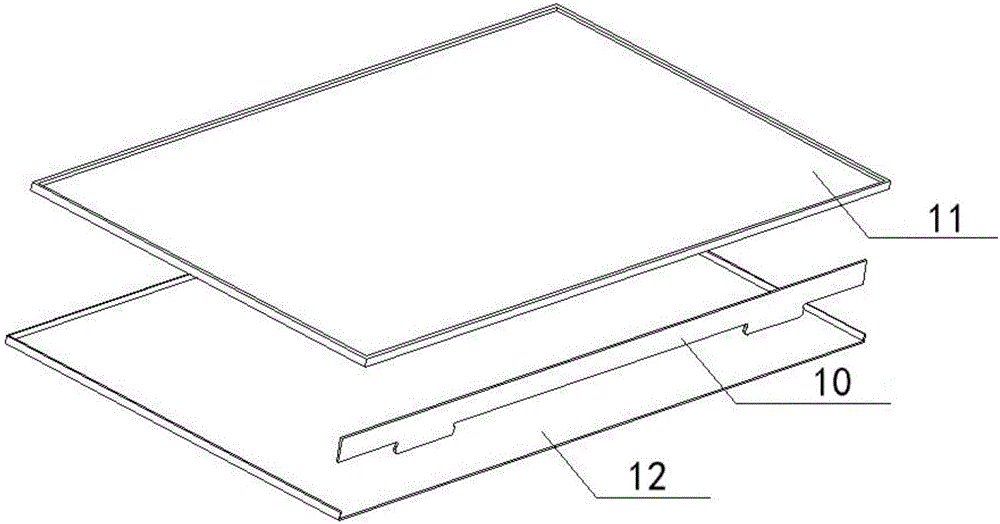
[0025] Such as image 3 As shown, the present invention also provides a liquid crystal display, including a backlight strip 10, a display screen 11, and a rear panel 12. The backlight strip is the LED backlight strip described in Embodiment 1, and the same parts will not be repeated.

[0026] In the liquid crystal display provided by this embodiment, since the light-emitting unit is placed in the U-shaped groove formed by the two light-shielding strips and the substrate, arbitrary adjustment of the surface of the light-emitting groove of the backlight light bar is realized, and the liquid crystal display device is realized under the condition of complete light-shielding. Ultra narrow bezels.

Embodiment 3

[0028] Such as Figure 4 As shown, the present invention also provides a panel light, including a backlight strip 10, a light-emitting panel 21, and a base plate 22. The backlight strip is the LED backlight strip described in Embodiment 1, and the same parts will not be repeated.

[0029] The panel light provided in this embodiment, because the light-emitting unit is placed in the U-shaped groove formed by the two light-shielding strips and the substrate, the surface of the light-emitting groove of the backlight light bar can be adjusted arbitrarily, and the panel-type lighting device can be realized under the condition of complete shading ultra-narrow bezel.


PUM


Abstract

The invention provides an LED backlight light bar. The LED backlight light bar comprises a substrate, light shading strips and light-emitting units at a minimum. The light shading strips are made of a long-strip-shaped elastic temperature-resistant material and bonded onto the substrate in the length direction. The light-emitting units are assembled in a U-shaped groove formed by the two light shading strips and the substrate. By means of the LED backlight light bar, a display device and a panel light can each be provided with an ultra-narrow frame under the condition that light is shielded completely; a product can be attractive in appearance; and materials are also saved.

Description

technical field [0001] The invention relates to an optical device, in particular to an LED backlight strip. Background technique [0002] At present, LED backlight strips commonly used in display devices and panel lights are mainly assembled with a plurality of light-emitting units 2 on a strip substrate 1 (see figure 1 ), and at the same time, in order to avoid side light leakage, the frame of the display device and the panel light needs to be wider, which not only looks unsightly, but also wastes materials. [0003] In order to realize the ultra-narrow bezel visual effect, a new type of LED backlight light bar is urgently needed. Contents of the invention [0004] The purpose of the present invention is to provide an LED backlight light bar capable of realizing the visual effect of an ultra-narrow frame. [0005] In order to solve the above problems, the present invention provides an LED backlight strip, which at least includes: a substrate, a light-shielding strip, an...

Claims


Application Information

Patent Timeline
IPC IPC(8): F21K9/20F21K9/60F21V17/10G02F1/13357F21Y103/10F21Y115/10
CPCG02F1/133603F21V17/101
Inventor 傅希全陈良旺申崇渝刘国旭代杰王宪刚
Owner SHINEON BEIJING TECH
Why Eureka
Try Eureka