Gas-inflating-and-locking-integrated gas blaster

An all-in-one, blaster technology, used in blasting cylinders, valves for inflation, compressed gas generation, etc., can solve problems such as low pyrolysis efficiency, poisonous pollution in blasting sites, and coal dust explosions.

Inactive Publication Date: 2017-05-10
郭远军
View PDF1 Cites 10 Cited by
  • Summary
  • Abstract
  • Description
  • Claims
  • Application Information

AI Technical Summary

Problems solved by technology

[0006] Adopt the gas blaster of above-mentioned detonator structure, existing problem is: 1, the thermal reaction material that needs to fill in the detonator needs to carry out the processing of processes such as material mixing, mixing evenly, rolling material or bagging, filling process It is time-consuming and labor-intensive, and the manufacturing cost is high; 2. During the filling process of the detonator, the oxidant and reducing agent are prone to uneven mixing, resulting in low heat release efficiency; 3. The thermal reaction material needs to be mixed and filled in advance. If the medium temperature is too high, it will easily cause combustion or explosion, which has great potential safety hazards; 4. Due to the damp, deterioration or deformation of the detonating material, it is easy to cause squibs, and it is impossible to determine the cause of the squibs, so it cannot pass The squib method eliminates potential safety hazards; 5. The detonation method of the existing gas blaster uses a solid activator to burn to generate high temperature, which directly conducts heat to the liquid carbon dioxide, causing the liquid carbon dioxide to gasify and expand, and the heat absorption efficiency of the liquid carbon dioxide is low; 6. The detonator The heat release rate is slow, the chemical reaction is insufficient, the heat release efficiency is low, the pressure of the liquid is relatively small after gasification, and the blasting power is small; 7. After the blas...

Method used


Image

  • Gas-inflating-and-locking-integrated gas blaster
  • Gas-inflating-and-locking-integrated gas blaster
  • Gas-inflating-and-locking-integrated gas blaster

Examples


Embodiment 1

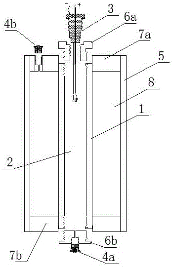
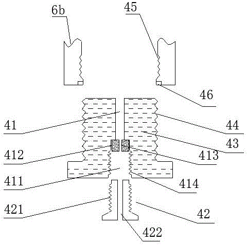
[0101] An inflatable and air-locked integrated gas blaster, such as figure 1 As shown, it includes an inner tube 1, an inner tube filling cavity 2, an ignition mechanism 3, an inner tube inflation mechanism 4a and an outer tube 5, the inner tube 1 is an inner tube filling cavity 2, and the two ends of the inner tube 1 are respectively sealed and connected with The first sealing inner cover 6a and the second sealing inner cover 6b, the outer layer of the inner tube 1 is the outer tube 5, and the first sealing outer cover 7a and the second sealing outer cover 7b are sealingly connected between the inner tube 1 and the outer tube 5 , the first sealing cover 7a and the second sealing cover 7b are located at both ends of the outer tube 5,

[0102] The sealed cavity between the inner tube 1 and the outer tube 5 is the outer tube filling cavity 8, and the inner tube filling cavity 2 is filled with a reducing agent and an oxidizing agent, and the oxidizing agent is supercritical oxyge...

Embodiment 2

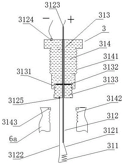
[0117] The difference with embodiment 1 is: as Figure 5 As shown, the ignition mechanism 3 includes a heating wire 311, a wire 312, a wire through hole 313 and a sealing base 314, the heating wire 311 is connected to the wire 312, and the axial center of the sealing base 314 is a wire through hole 313, and the wire 312 is wrapped through the insulating layer. Wire perforation 313; the upper end of the wire perforation 313 is an internally threaded hole 3131, and an internal sealing rubber ring 3132 is installed at the bottom of the internally threaded hole 3131. The internally threaded hole 3131 is matched with a perforating screw 3133, and the axis of the perforating screw 3133 is provided with a perforation, and the wire 312 passes through the inner sealing rubber ring 3132 and the perforated screw 3133, and the perforating screw 3133 cooperates with the internal thread hole 3131 to press the inner sealing rubber ring 3132 to seal the wire hole 313; the outer wall of the sea...

Embodiment 3

[0119] The difference with embodiment 1 or 2 is: as Figure 6 As shown, the inner tube 1 includes a first segmented body 11 and a second segmented body 12, the first segmented body 11 and the second segmented body 12 are connected through a threaded structure, and are matched with a threaded sealing ring 13 for Sealing; the first sealing inner cover 6a and the second sealing inner cover 6b are respectively connected to both sides of the first segment body 11 and the second segment body 11; this structure is convenient for charging.


PUM

PropertyMeasurementUnit
Tensile strengthaaaaaaaaaa

Abstract

The invention discloses a gas-inflating-and-locking-integrated gas blaster. The gas-inflating-and-locking-integrated gas blaster comprises an inner tube, an inner-tube filling cavity, an ignition mechanism, an inner-tube gas inflating mechanism and an outer tube. The inner-tube filling cavity is formed in the inner tube, a first sealing inner cover and a second sealing inner cover are connected to the two ends of the inner tube in a sealed mode respectively, the outer tube is arranged on the outer layer of the inner tube, a first sealing outer cover and a second sealing outer cover are connected between the inner tube and the outer tube in a sealed mode, the ignition mechanism and the inner-tube gas inflating mechanism are installed on the first sealing inner cover or the second sealing inner cover, and an outer-tube gas inflating mechanism is installed on the first sealing outer cover or the second sealing outer cover; a sealed cavity between the inner tube and the outer tube is an outer-tube filling cavity, the inner-tube filling cavity is filled with supercritical oxygen and carbonaceous organic materials, and the outer-tube filling cavity is filled with liquid easy-to-gasify materials such as liquid carbon dioxide or liquid nitrogen. The gas-inflating-and-locking-integrated gas blaster has the advantages that the manufacturing cost is low, the mixing uniformity of reaction materials is high, the heat releasing efficiency is high, the transportation safety is good, and the blasting power is large.

Description

technical field [0001] The invention belongs to the technical field of blasters, in particular to an integrated gas blaster with air charging and air lock. Background technique [0002] Gas blasting technology is to use the vaporization and expansion of easily vaporized liquid or solid substances to generate high-pressure gas, which makes the surrounding medium expand to do work and cause fragmentation. It has the characteristics of no open flame, safety and high efficiency. [0003] Carbon dioxide gas blasters are typical blasting equipment in gas blasting technology, and are widely used in mining, geological exploration, cement, steel, electric power and other industries, subways and tunnels, municipal engineering, underwater engineering, and emergency rescue. [0004] The existing gas blaster mainly includes a vaporization liquid storage pipe and a heating detonator installed in the vaporization liquid storage pipe; the heating detonator ignites and generates heat to vapo...

Claims


Application Information

Patent Timeline
IPC IPC(8): F42B3/04F42B3/28F42B3/10F42B3/103F42B3/11F42B3/18C06D5/10C06B47/12C06B47/06C06B47/02C06B27/00F16K15/02F16K24/06
CPCC06B27/00C06B47/02C06B47/06C06B47/12C06D5/10F16K15/02F16K24/06F42B3/045F42B3/10F42B3/103F42B3/11F42B3/18F42B3/28Y02P20/10Y02P20/54
Inventor 郭远军
Owner 郭远军
Why Eureka
Try Eureka