Air conditioner system and control method thereof

An air-conditioning system and refrigerant technology, applied in air-conditioning systems, heating and ventilation control systems, heating and ventilation safety systems, etc., can solve problems such as insufficient dehumidification and insufficient heating, so as to avoid insufficient dehumidification and reduce energy consumption , Improve the effect of energy consumption ratio

Active Publication Date: 2016-11-23
DAIKIN IND LTD
View PDF9 Cites 1 Cited by
  • Summary
  • Abstract
  • Description
  • Claims
  • Application Information

AI Technical Summary

Problems solved by technology

However, when the above-mentioned structure is used for heating and dehumidification, since the same part of the heat of the refrigerant is first used for heating and then taken away by the airflow, and then used for cooling, neither the dehumidification heat exchanger 21X1 nor the heating heat exchanger 22X can fully play their role , that is, insufficient dehumidification and insufficient heating

Method used


Image

  • Air conditioner system and control method thereof
  • Air conditioner system and control method thereof
  • Air conditioner system and control method thereof

Examples


Embodiment approach 1

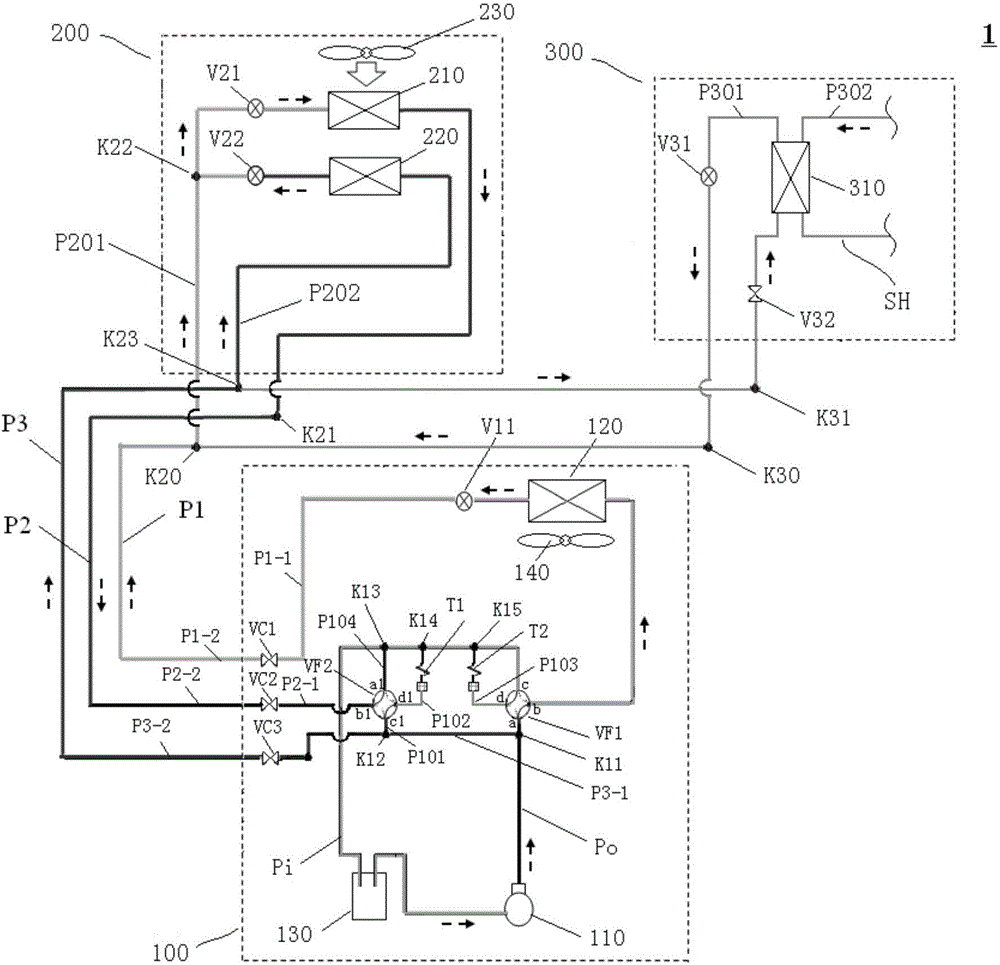
[0141] First, refer to figure 1 , the circuit configuration of the air conditioning system 1 according to Embodiment 1 will be described in detail.

[0142] Such as figure 1 As shown, the air conditioning system 1 of this embodiment includes an outdoor unit 100, a dehumidifying and heating indoor unit 200, and a refrigerant-water heat exchange unit 300. A plurality of connection pipes including the one connection pipe P1, the second connection pipe P2, and the third connection pipe P3 are connected to each other.

[0143] Here, stop valves VC1 to VC3 are provided in the middle of the first connection pipe P1, the second connection pipe P2, and the third connection pipe P3 (hereinafter, the range of the outdoor unit is also delimited by the stop valves VC1 to VC3). , and the first connection piping P1, the second connection piping P2 and the third connection piping P3 are divided into the first part P1-1~P3-1 and the second part P1-2~P3- with the stop valve VC1~VC3 as the b...

Embodiment approach 2

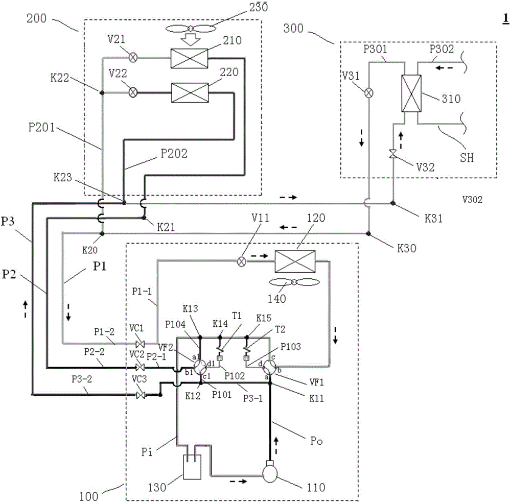
[0204]First, refer to Figure 5 , to describe the circuit structure of the air conditioning system 1A according to Embodiment 2 of the present invention, wherein, in figure 2 In , the same reference numerals are given to the same components as those in Embodiment 1 described above.

[0205] In addition, since the air-conditioning system 1A of Embodiment 2 is basically the same as the air-conditioning system 1 of the above-mentioned Embodiment 1 in terms of configuration, differences from the above-mentioned Embodiment 1 will be mainly described below.

[0206] In this embodiment, an end (located at the Figure 5 end at midpoint K16) branch pipe P105 connected to suction pipe Pi.

[0207] And, the third connecting pipe P3 has a first part P3-1 (from Figure 5 The part from point K11 in the following four-way switching valve VF3 to the port a2 of the following four-way switching valve) and the second part P3-2 (from the port b2 of the following four-way switching valve VF3 t...

Embodiment approach 3

[0239] Below, refer to Figure 7 The air conditioning system 1B according to Embodiment 3 of the present invention will be described, in which Figure 7 In , the same reference signs are attached to the same components as those in Embodiment 2 above.

[0240] In addition, since the air-conditioning system 1B of this embodiment is basically the same as the air-conditioning system 1A of the said 2nd Embodiment in terms of structure, it demonstrates centering on the difference from the said 2nd Embodiment below.

[0241] In this embodiment, if Figure 7 As shown, the air-conditioning system 1B further includes indoor units 400A and 400B in addition to the air-conditioning system 1A according to the second embodiment. One end of P401A, P401B ( Figure 7 The ends located at points K40A and K40B) are connected to the part of the first connection pipe P1 outside the outdoor unit 100, and the other ends of these indoor unit side refrigerant pipes P401A and P401B ( Figure 7 The en...


PUM


Abstract

The invention provides an air conditioner system and a control method thereof. According to the air conditioner system and the control method thereof, fluid subjected to sufficient dehumidification and heating can be supplied into a room in an energy saving mode, and a hot water supply function is achieved. The air conditioner system comprises an outdoor unit and a dehumidification and heating indoor unit which are connected through a first connecting piping, a second connecting piping and a third connecting piping. The air conditioner system further comprises a refrigerant water-heat exchange unit, a first switching device and a second switching device, wherein the refrigerant water-heat exchange unit comprises a refrigerant piping, a water loop and a refrigerant water-heat exchanger; one end of the refrigerant piping is connected with the first connecting piping, and the other end of the refrigerant piping is connected with the third connecting piping; the first switching device can be switched between the state that a discharge pipe communicates with the first connecting piping and the state that the first connecting piping communicates with a suction pipe; and the second switching device can be switched between the state that the second connecting piping communicates with the suction pipe and the state that the second connecting piping communicates with the third connecting piping.

Description

technical field [0001] The present invention relates to an air-conditioning system and a control method thereof, in particular to an air-conditioning system including an outdoor unit and a dehumidifying and heating indoor unit and a control method thereof. Background technique [0002] With the improvement of people's living standards, people's demand for living environment control has become increasingly prominent. Therefore, the function of the air conditioning system has gradually developed from a single temperature adjustment to a diversified development. In humid and rainy areas and during the rainy season, the humidity of the air is high, causing discomfort to the human body. Therefore, an air-conditioning system with a humidity control function has emerged as the times require. [0003] Air conditioning systems typically dehumidify by passing air through a heat exchanger whose surface temperature is below the dew point of the air, causing the air to condense and there...

Claims


Application Information

Patent Timeline
IPC IPC(8): F24F5/00F24F11/02F24F13/30
Inventor 冈本敦赵俊宇蔡耿新
Owner DAIKIN IND LTD
Why Eureka
Try Eureka