Thimble sealed type trigger and cracking device

A sealed and detonator technology, applied in the direction of blasting barrels, weapon accessories, functional valve types, etc., can solve the problems of eliminating potential safety hazards, low blasting power, and high manufacturing costs, so as to avoid potential safety hazards, reduce costs, and save mixing materials Effect

Inactive Publication Date: 2017-04-26
郭远军
View PDF1 Cites 1 Cited by
  • Summary
  • Abstract
  • Description
  • Claims
  • Application Information

AI Technical Summary

Problems solved by technology

[0006] The detonator with the above structure has the following problems: 1. The thermal reactants to be filled in the detonator need to be processed by mixing, mixing, coiling or bagging, and the filling process is time-consuming. 2. During the filling process of the detonator, the oxidant and reducing agent are prone to uneven mixing, resulting in low heat release efficiency; 3. The thermal reaction material needs to be mixed and filled in advance, and the temperature during transportation is too high. It is highly likely to cause combustion or explosion, and has a greater potential safety hazard; 4. Due to the delay of the detonating material or other situations, it is easy to appear the situation of squibs, and it is impossible to judge the cause of the squibs, so it cannot be eliminated by rowing the squibs Potential safety hazard; 5. The detonation method of the existing gas blaster uses a solid activator to burn to generate high temperature, which directly conducts heat to the liquid carbon dioxide, causing the liquid carbon dioxide to gasify and expand, and the heat absorption efficiency of the liquid carbon dioxide is low; 6. The heat release of the detonator The speed is slow, the chemical reaction is insufficient, the thermal release efficiency is low, the pressure of the liquid is relatively small after gasification, and the blasting power is small; 7. After the blasting, the reactants in the detonator produce a large amount of toxic and harmful gases, such as sulfur Gases such as hydrogen, sulfur dioxide, nitric oxide, and nitrogen dioxide bring relatively large poisonous pollution to the blasting site
[0007] In addition, since the sealing ball in the conventional inflatable valve is located at the bottom of the valve stem, when the sealing ball is squeezed too much by the valve stem, the sealing ball will be damaged and deformed, which leads to the subsequent use of the sealing ball after passing the pressure test. There may be air leakage in normal use

Method used


Image

  • Thimble sealed type trigger and cracking device
  • Thimble sealed type trigger and cracking device
  • Thimble sealed type trigger and cracking device

Examples


Embodiment 1

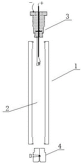
[0079] A thimble sealed detonator, such as figure 1 As shown, it includes a housing 1, a filling chamber 2, an ignition mechanism 3 and an inflatable mechanism 4. The housing 1 is filled with a chamber 2, and the housing 1 is sealed to connect the ignition mechanism 3 and the inflatable mechanism 4. The pressure resistance of the housing 1 The strength is greater than 5.045Mpa; the shell 1 is a carbon steel cylinder or a stainless steel cylinder, and the inflation mechanism 4 and the ignition mechanism 3 are respectively connected to both ends of the shell 1; the filling chamber 2 is filled with a reducing agent and an oxidizing agent, and the oxidizing agent It is liquid oxygen, supercritical oxygen or high-pressure gaseous oxygen, and the reducing agent is carbon-containing organic matter or reducing element;

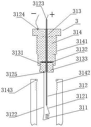
[0080] Such as figure 2 As shown, the ignition mechanism 3 includes a heating wire 311, a wire 312, a wire through hole 313 and a sealing base 314, the heating wire...

Embodiment 2

[0090] The difference with embodiment 1 is: as Figure 5 As shown, the ignition mechanism 3 includes a heating wire 311, a wire 312, a wire through hole 313 and a sealing base 314, the heating wire 311 is connected to the wire 312, and the axial center of the sealing base 314 is a wire through hole 313, and the wire 312 is wrapped through the insulating layer. Wire perforation 313; the upper end of the wire perforation 313 is an internally threaded hole 3131, and an internal sealing rubber ring 3132 is installed at the bottom of the internally threaded hole 3131. The internally threaded hole 3131 is matched with a perforating screw 3133, and the axis of the perforating screw 3133 is provided with a perforation, and the wire 312 passes through the inner sealing rubber ring 3132 and the perforated screw 3133, and the perforating screw 3133 cooperates with the internal thread hole 3131 to press the inner sealing rubber ring 3132 to seal the wire hole 313; the outer wall of the sea...

Embodiment 3

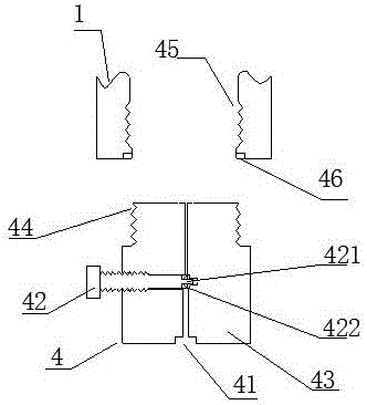
[0092] The difference with embodiment 1 or 2 is: as Image 6 As shown, the housing 1 includes a first segment body 11 and a second segment body 12, the first segment body 11 and the second segment body 12 are connected through a threaded structure, and are matched with a threaded sealing ring 13 for Sealing; the inflation mechanism 4 and the ignition mechanism 3 are respectively connected to both sides of the first segment body 11 and the second segment body 11; this structure is convenient for charging.


PUM

PropertyMeasurementUnit
Compressive strengthaaaaaaaaaa
Thicknessaaaaaaaaaa
Inner diameteraaaaaaaaaa

Abstract

The invention discloses a thimble sealed type trigger and a cracking device. The thimble sealed type trigger comprises a shell, a filling cavity, an ignition mechanism and an air inflation mechanism. The inside of the shell is the filling cavity, and the shell is connected with the sealed ignition mechanism and the air inflation mechanism. The filling cavity is filled with supercritical oxygen and carbonaceous organic material or elementary substance with reductibility. The air inflation mechanism comprises an air inflation hole, a valve rod and an air inflation valve seat. The middle of the air inflation hole is an air locking cavity, and the valve rod is movably installed in the air locking cavity through a thread structure. An ejector header and an ejector header sealed ring are installed at the top of the valve rod, and the ejector header is sleeved with the ejector header sealed ring. The thimble sealed type trigger and the cracking device have the advantages that manufacturing cost is low, mixing uniformity of reaction materials is high, heat releasing efficiency is high, and conveying safety is good.

Description

technical field [0001] The invention belongs to the technical field of detonators, and in particular relates to a thimble-sealed detonator and a cracker. Background technique [0002] Gas blasting technology is to use the vaporization and expansion of easily vaporized liquid or solid substances to generate high-pressure gas, which makes the surrounding medium expand to do work and cause fragmentation. It has the characteristics of no open flame, safety and high efficiency. [0003] Carbon dioxide gas blasters are typical blasting equipment in gas blasting technology, and are widely used in mining, geological exploration, cement, steel, electric power and other industries, subways and tunnels, municipal engineering, underwater engineering, and emergency rescue. [0004] The existing gas blaster mainly includes a vaporization liquid storage pipe and a heating detonator installed in the vaporization liquid storage pipe; the heating detonator ignites and generates heat to vapori...

Claims


Application Information

Patent Timeline
IPC IPC(8): F42B3/04F42B3/10F42B3/103F42B3/11F42B3/28F42B3/24C06B47/12C06B47/06C06B47/02F16K1/02F16K1/32F16K24/06
CPCC06B47/02C06B47/06C06B47/12F16K1/02F16K1/32F16K24/06F42B3/045F42B3/10F42B3/103F42B3/11F42B3/24F42B3/28Y02P20/10Y02P20/54
Inventor 郭远军
Owner 郭远军
Why Eureka
Try Eureka