
Single-center projection transformation method of multi-lens and multi-detector aerial camera
A technology of center projection and conversion method, applied in the field of aero-optical remote sensing, which can solve the problems of rarely answering precision control problems, rarely publicizing core problems, and failing to clarify the process of converting multi-center projection to single-center projection.
- Summary
- Abstract
- Description
- Claims
- Application Information
AI Technical Summary
Problems solved by technology
Method used
Image

Examples
Embodiment Construction
[0046] Specific embodiments of the present invention are further described in detail below.
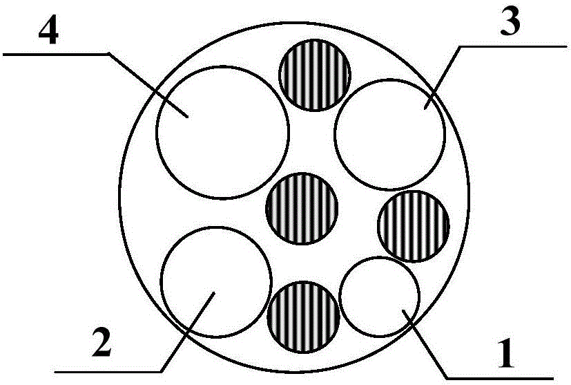
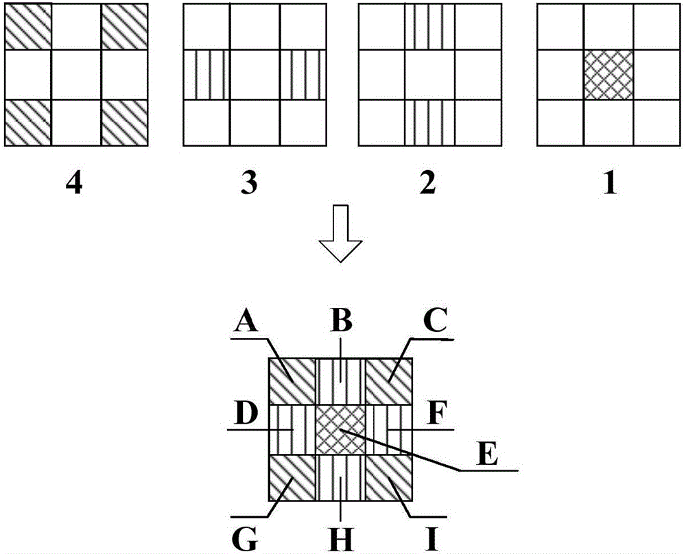
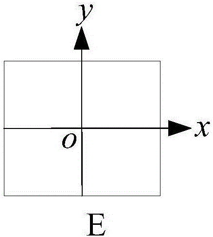
[0047] 1) for figure 1 The lens diagram of the multi-lens and multi-detector aerial camera shown, 1, 2, 3 and 4 represent four panchromatic lenses, and the corresponding four cameras (hereinafter referred to as panchromatic lens 1~4 cameras) are polycentric projections Imaging, the number and distribution of detectors contained in each, see figure 2 . figure 2 A~I in the table represent the number of detectors: E is the center detector, corresponding to figure 1 The panchromatic lens 1; B, H corresponding figure 1 The panchromatic lens 2; D, F corresponding figure 1 Panchromatic lens 3; A, C, G, I corresponding figure 1 Panchromatic lens4. choose figure 2 The image of the center detector E in is used as the reference image, and its geometric center point is taken as the origin o of the image plane coordinate system to construct a right-hand plane Cartesian coordinate system,...
PUM
 Abstract
Description
Claims
Application Information