
Terminal capacitance type proximity sensor-enabled control device, terminal and method

A technology of proximity sensors and control devices, which is applied in the field of terminal capacitive proximity sensor enabling control devices, and can solve problems such as power consumption and user false touches

Inactive Publication Date: 2017-05-10
NUBIA TECHNOLOGY CO LTD
View PDF5 Cites 1 Cited by
  • Summary
  • Abstract
  • Description
  • Claims
  • Application Information

AI Technical Summary

Problems solved by technology

[0003] The main purpose of the present invention is to provide a terminal capacitive proximity sensor enabling control device, terminal and method, aiming to solve the problem that in the prior art, the capacitive proximity sensor in the terminal is always in the open state, which may cause the user to accidentally touch, and Problems that consume a lot of power

Method used


Image

  • Terminal capacitance type proximity sensor-enabled control device, terminal and method
  • Terminal capacitance type proximity sensor-enabled control device, terminal and method
  • Terminal capacitance type proximity sensor-enabled control device, terminal and method

Examples


no. 1 example

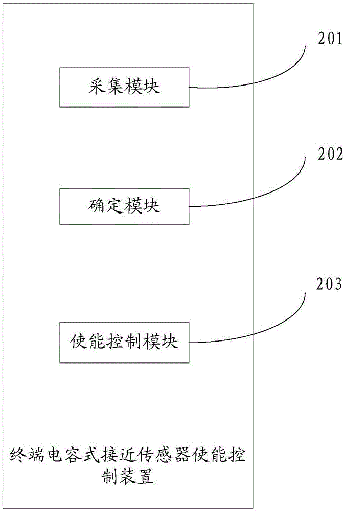
[0047] This embodiment provides a terminal capacitive proximity sensor enabling control device, see figure 2 , figure 2 A schematic diagram of a terminal capacitive proximity sensor enabling control device provided in the first embodiment of the present invention, the terminal capacitive proximity sensor enabling control device includes: an acquisition module 201, a determination module 202, and an enabling control module 203, wherein ,

[0048] The collection module 201 is configured to collect control information for enabling control of the terminal capacitive proximity sensor.

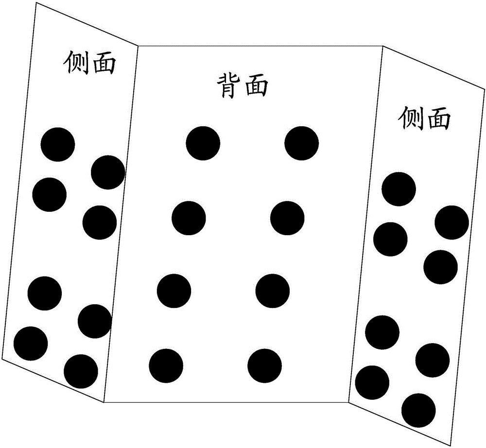
[0049] In this embodiment, multiple capacitive proximity sensors are provided on both side frames and the back of the terminal. The capacitive proximity sensors have the advantages of simple structure, high sensitivity, good dynamic response characteristics, strong adaptability, high overload resistance and low price. It is mainly used to measure parameters such as pressure, force, displacement ...

no. 2 example

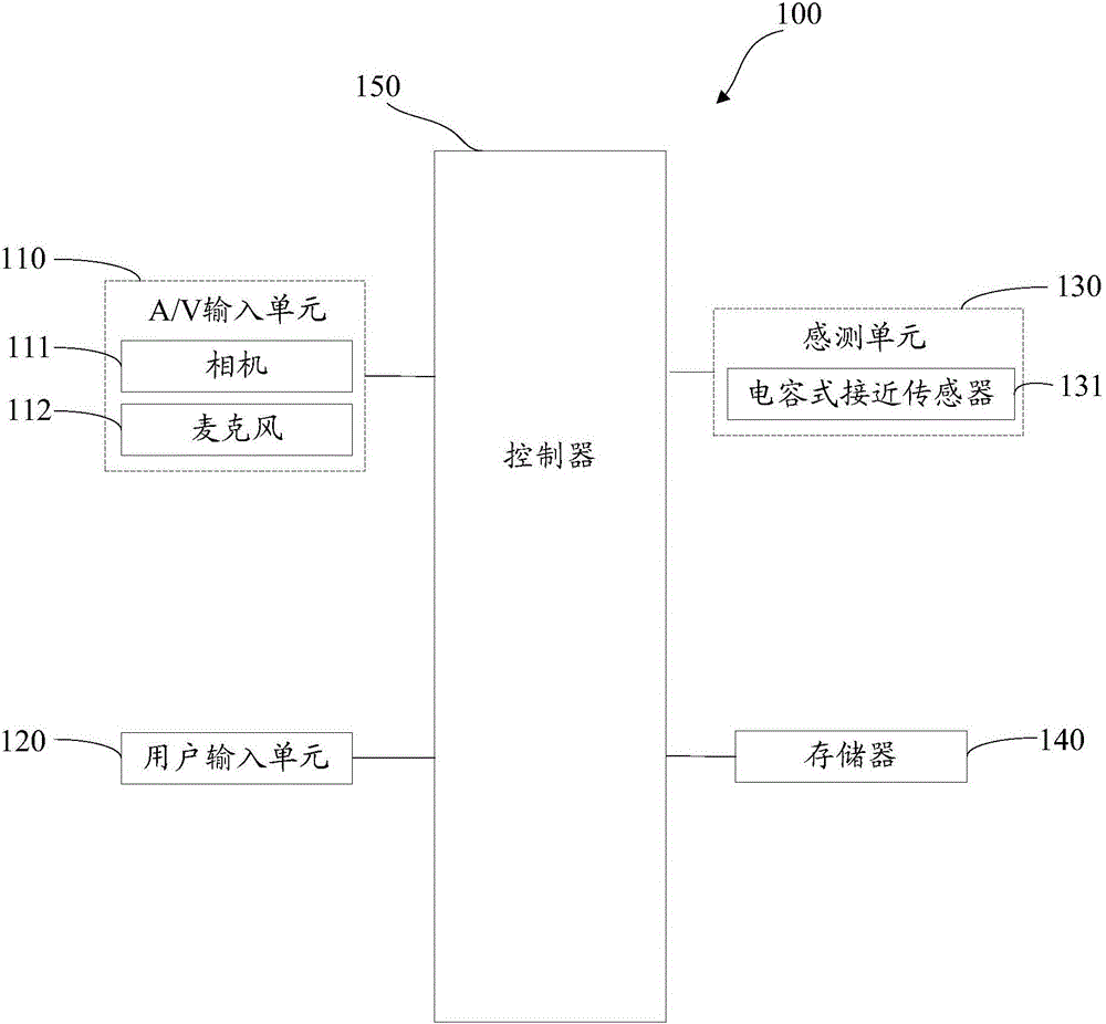
[0089] This embodiment provides a terminal, see Figure 5 , Figure 5 It is a schematic diagram of a terminal provided by the second embodiment of the present invention, the terminal includes the terminal capacitive proximity sensor enabling control device in the first embodiment. The functions performed by each functional module of the above-mentioned terminal capacitive proximity sensor enabling control device can be passed figure 1 Part of the hardware is implemented, of course, the functions performed by each hardware can also be implemented by the above functional modules. The functions of the above functional modules are specifically realized by the following hardware:

[0090] The function of the acquisition module 201 can be realized through the user input unit 120 or the microphone 112, and the user input unit 110 can generate key input data according to commands input by the user to control various operations of the terminal. The user input unit 110 allows the use...

no. 3 example

[0133] This embodiment provides a terminal capacitive proximity sensor enabling control method, see Figure 6 , Figure 6 The flow chart of the terminal capacitive proximity sensor enabling control method provided by this embodiment includes the following steps:

[0134] S601: Collect control information for enabling control of the terminal capacitive proximity sensor.

[0135] In this embodiment, multiple capacitive proximity sensors are provided on both side frames and the back of the terminal. The capacitive proximity sensors have the advantages of simple structure, high sensitivity, good dynamic response characteristics, strong adaptability, high overload resistance and low price. It is mainly used to measure parameters such as pressure, force, displacement and vibration.

[0136] Multiple capacitive proximity sensors are provided on both side frames and the back of the terminal. The total number of capacitive proximity sensors can be three, that is, one on each side of ...


PUM


Abstract

The invention discloses a terminal capacitance type proximity sensor-enabled control device, terminal and method. The terminal capacitance type proximity sensor-enabled control device comprises a collecting module, a determining module and an enabled control module, wherein the acquisition module is used for collecting control information which is used for conducting enabled control on terminal capacitance type proximity sensors; the determining module is used for determining an enabled control instruction corresponding to the control information through a locking and unlocking control unit in the terminal; the enabled control module is used for conducting enabled control on all the capacitance type proximity sensors arranging on the back side of the terminal and in two side frames of the terminal according to the enabled control instruction. By means of the device, when the capacitance type proximity sensors need to be used, the capacitance type proximity sensors are unlocked through the locking and unlocking control unit so as to enable the device to be in an operating state, and when the capacitance type proximity sensors do not need to be used, the capacitance type proximity sensors are locked through the lock locking and unlocking control unit so as to enable the device to be in a non-operating state. The situation of touching by mistake is avoided, the user experience is improved, and the power consumption is reduced.

Description

technical field [0001] The present invention relates to the technical field of terminals, and more specifically, to a terminal capacitive proximity sensor enabling control device, terminal and method. Background technique [0002] With the development of terminal technology, the functions of the terminal are becoming more and more abundant. At present, the terminal is equipped with a capacitive proximity sensor. When the terminal is in the power-on state, the capacitive proximity sensor is always on, which may cause the user to accidentally touch it. , the user experience is poor, and it consumes a lot of power. Contents of the invention [0003] The main purpose of the present invention is to provide a terminal capacitive proximity sensor enabling control device, terminal and method, aiming to solve the problem that in the prior art, the capacitive proximity sensor in the terminal is always in the open state, which may cause the user to accidentally touch, and A problem ...

Claims


Application Information

Patent Timeline
Patent Type & Authority Applications(China)
IPC IPC(8): G06F3/041G06F3/044G06F1/32H04M1/725
CPCG06F1/325G06F3/0416G06F3/044H04M1/72454H04M1/72463Y02D30/70
Inventor 杨奎汪健
Owner NUBIA TECHNOLOGY CO LTD
Learn More