Gas relay for transformer protection

A gas relay, transformer protection technology, applied in the direction of circuit, electric switch, electrical components, etc., can solve the problems of transformer oil accidental contact, inability to monitor, and transformer can not achieve accurate control and understanding, so as to reduce false alarms , to avoid the effect of accidental touch

Inactive Publication Date: 2021-09-07
郭渗渗
View PDF0 Cites 0 Cited by
  • Summary
  • Abstract
  • Description
  • Claims
  • Application Information

AI Technical Summary

Problems solved by technology

[0003] In the gas relay, when the gas is generated to a certain amount, the upper floating ball will fall to the position where it touches the contact. Although this can play the role of alarm, it cannot play the role of monitoring, that is, just inside the gas relay It is impossible to detect when the gas has already remained at the beginning, so that the internal situation of the transformer cannot be accurately controlled, and the floating ball can only trigger the signal when the gas reaches the maximum state. There is also a certain danger. At the same time, this There may also be false touches in the case of a limit contact, resulting in false alarms;
[0004] When heavy gas occurs, it will drive the transformer oil to surge to the oil conservator. At this time, the contact will be touched by the impact of the surge on the baffle. In this case, the trip switch can only be triggered when the surge speed reaches a certain level. Understand the size of the instantaneous inrush current, and it is impossible to detect how long the inrush current will stop after tripping, and there is still a possibility of false touch when the transformer oil has a flow of thermal expansion and contraction, and it cannot accurately play the role of detection and alarm

Method used


Image

  • Gas relay for transformer protection
  • Gas relay for transformer protection
  • Gas relay for transformer protection

Examples


Embodiment Construction

[0021] The following will clearly and completely describe the technical solutions in the embodiments of the present invention with reference to the accompanying drawings in the embodiments of the present invention. Obviously, the described embodiments are only some, not all, embodiments of the present invention. Based on the embodiments of the present invention, all other embodiments obtained by persons of ordinary skill in the art without making creative efforts belong to the protection scope of the present invention.

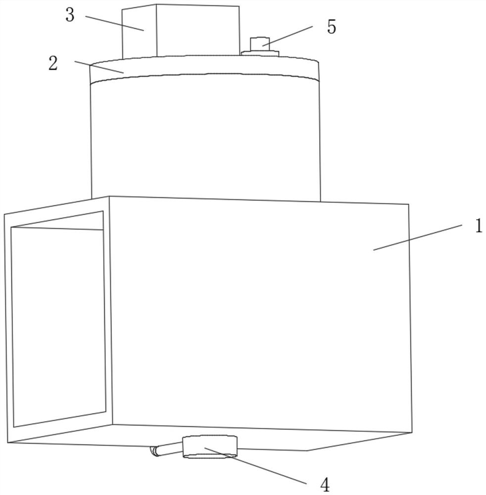
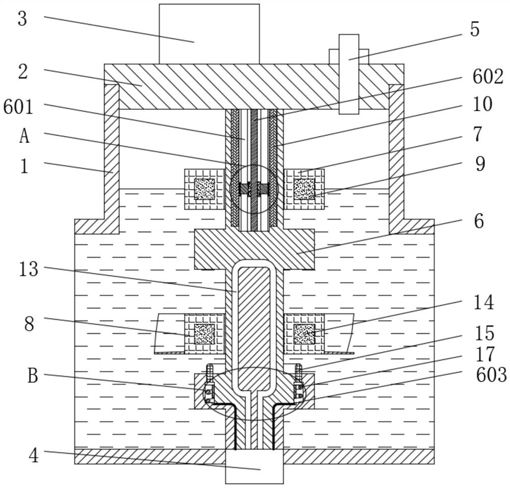
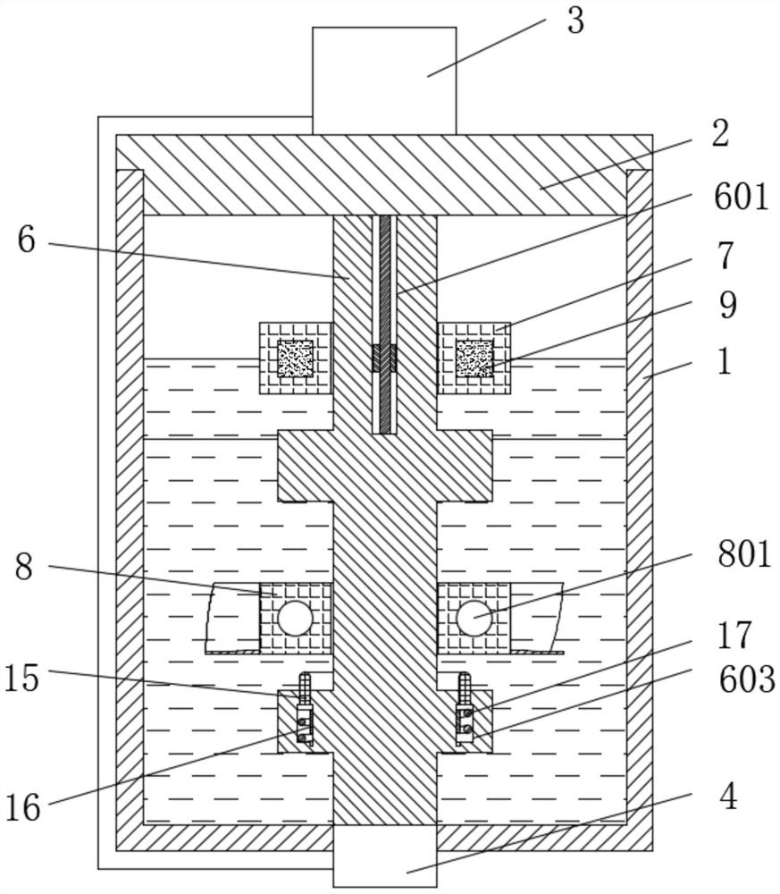
[0022] see Figure 1-7 , a gas relay for transformer protection, comprising a casing 1, a top cover 2 is fixedly sleeved on the top of the casing 1, a control box 3 is fixedly installed on one side of the top surface of the top cover 2, and a control box 3 is fixedly installed on the other top surface of the top cover 2 The air plug 5 is fixedly installed on the side, the signal box 4 is fixedly installed in the middle of the bottom surface of the housing 1, t...


PUM


Abstract

The invention relates to the technical field of transformer protection, and discloses a gas relay for transformer protection. A supporting sleeve shaft is fixedly mounted in the middle of the interior of a shell, a first floating ring movably sleeves the outer ring of the upper half portion of the supporting sleeve shaft, and an annular magnet is fixedly mounted in the first floating ring. The outer ring of the lower half portion of the supporting sleeve shaft is movably sleeved with a second floating ring. Resistor strips are symmetrically and fixedly installed on the two sides of the sliding groove respectively, a sliding rod is fixedly installed in the center of the sliding groove, the outer ring of the sliding rod is movably sleeved with a conductive magnetic ring, and the two sides of the conductive magnetic ring are fixedly connected with sliding pieces making contact with the resistor strips through conductive rods. The resistor strips on the two sides can be connected through the sliding pieces. Arc magnets are symmetrically and fixedly installed in the two sides of the second floating ring. A wire is fixedly installed in the bottom end of the supporting sleeve shaft in a U shape. The sleeve shaft and the two floating rings work cooperatively and are matched with signal transmission, so that gas detection can be realized, and the false alarm condition can be avoided at the same time.

Description

technical field [0001] The invention relates to the technical field of transformer protection, in particular to a gas relay for transformer protection. Background technique [0002] In order to adapt to the thermal expansion and contraction of the transformer oil, an oil conservator is used to adjust the oil volume change in the transformer to ensure that the interior is properly filled with transformer oil. However, when a discharge fault occurs in the transformer oil, carbon monoxide and methane will be produced. and other harmful gases, and the greater the fault, the faster and more these gases will be generated. In order to ensure safety, it is necessary to install a gas relay between the transformer box and the oil conservator to realize the alarm function. According to the speed and amount of gas generated To touch the electric shock in the relay so as to realize the alarm signal and trip signal, but there are still some shortcomings in the similar structure of these e...

Claims


Application Information

Patent Timeline
Patent Type & Authority Applications(China)
IPC IPC(8): H01H36/00H01H35/18
CPCH01H36/0013H01H35/18
Inventor 郭渗渗
Owner 郭渗渗
Why Eureka
Try Eureka