An automatic plugging device

A technology for automatic plugging and unplugging, which is applied to the coupling device, the parts of the connecting device, and the connection/disconnection of the connecting device.

Active Publication Date: 2018-12-21
HUNAN RAMON SCI & TECH
View PDF10 Cites 0 Cited by
  • Summary
  • Abstract
  • Description
  • Claims
  • Application Information

AI Technical Summary

Problems solved by technology

[0006] The purpose of the present invention is to provide an automatic plugging and unplugging device, whose structural design can solve the problems of time-consuming and laborious plugging and unplugging, inability to switch between automatic control and manual operation, and inability to adapt to large deviations.

Method used


Image

  • An automatic plugging device
  • An automatic plugging device

Examples


Embodiment Construction

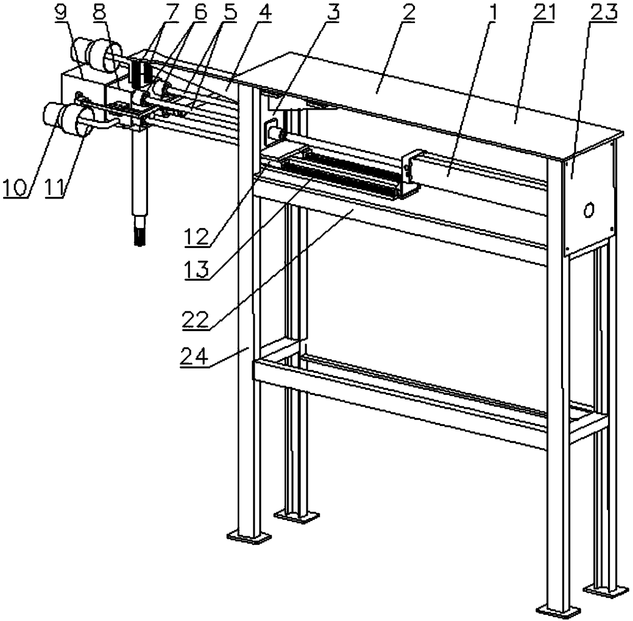
[0021] The core of the present invention is to provide an automatic plugging and unplugging device, whose structural design can solve the problems of time-consuming and laborious plugging and unplugging, inability to switch between automatic control and manual operation, and inability to adapt to large deviations.

[0022] In order to enable those skilled in the art to better understand the solution of the present invention, the present invention will be further described in detail below in conjunction with the accompanying drawings and specific embodiments.

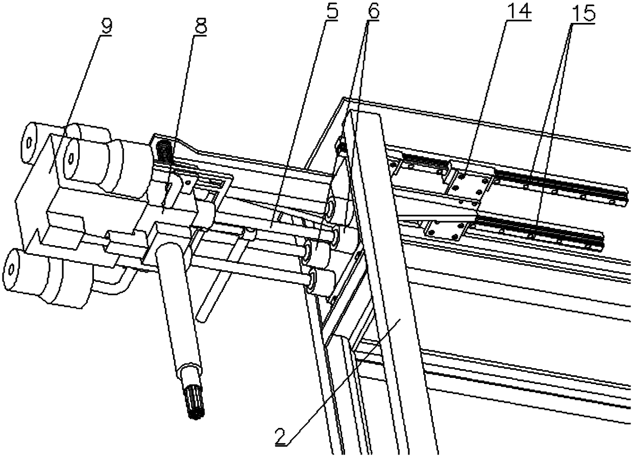
[0023] Please refer to figure 1 and figure 2 , figure 1 It is a structural schematic diagram of a specific embodiment of the automatic plugging and unplugging device provided by the present invention; figure 2 It is another schematic diagram of a specific embodiment of the automatic plugging and unplugging device provided by the present invention.

[0024] The automatic plugging and unplugging device provided by the...


PUM


Abstract

The invention discloses an automatic insertion and extraction device. The automatic insertion and extraction device comprises a bracket and a telescopic cylinder used for driving a plug to move forwards and backwards so as to be inserted in and extracted out of a socket; one end of the telescopic cylinder is fixedly arranged at the bracket while the other end of the telescopic cylinder is fixedly connected with a support connecting plate; a spherical hinge is arranged at the front side of the support connecting plate; the plug is arranged at the end part of the connecting rod of the spherical hinge; the support connecting plate is provided with an extension part which extends to the upside of the plug; the extension part is provided with a suspended spring; the top end of the plug is connected with the bottom end of the suspended spring; and the telescopic cylinder is controlled to drive the support connecting plate to further drive the plug to move forwards until the plug is aligned and stuck with the socket, so that automatic insertion and extraction of the plug and the socket is realized. As the support connecting plate is connected with the plug in a floating manner by utilizing the suspended spring and the spherical hinge, the plug can move upwards, downwards, leftwards and rightwards in a relatively big range; even the position deviation of the plug and the socket is relatively large, floating alignment also can be realized; and the automatic insertion and extraction device can be switched into a manual operating state after the spherical hinge and suspended spring connected with the plug are loosed.

Description

technical field [0001] The invention relates to the technical field of plugging and unplugging automation, in particular to an automatic plugging and unplugging device. Background technique [0002] With the development of the national iron and steel industry, intelligent manufacturing has attracted more and more attention. Torpedo tankers are used as equipment for storing and transporting molten iron. control and work. [0003] At present, most steel mills complete the plugging and unplugging of plugs and sockets manually, but the plugs of torpedo tank trucks are heavy. The space between the storage room and the control room is time-consuming and labor-intensive. In addition, the torpedo tank car plug storage room is full of dust, and the temperature reaches about 60 degrees Celsius. [0004] There are also very few steel mills that have realized the automatic insertion and removal of the plug and socket of the torpedo tank car, but its structure is relatively complicated...

Claims


Application Information

Patent Timeline
Patent Type & Authority Patents(China)
IPC IPC(8): H01R43/26H01R13/629H01R13/631
CPCH01R13/629H01R13/631H01R43/26
Inventor 田陆
Owner HUNAN RAMON SCI & TECH
Why Eureka
Try Eureka