Unhooking and resetting device

A technology of reset device and plug-in device, which is applied in fixing devices, fluid pressure actuating devices, transportation and packaging, etc., can solve the problems of high risk, labor-intensive, complicated decoupling and reset process, etc., so as to improve the test safety. The effect of simplifying the decoupling reset process

Pending Publication Date: 2021-06-18
ZHONGCHUAN NO 9 DESIGN & RES INST
View PDF0 Cites 0 Cited by
  • Summary
  • Abstract
  • Description
  • Claims
  • Application Information

AI Technical Summary

Problems solved by technology

[0003] At present, the existing decoupling reset device used for the free fall test of the elevator test tower, the insertion and extraction action of the safety pin 5 and the rotation and reset action of the swinging beam 10 generally use manipulators plus manual operation, the cost is high, and each decoupling action Afterwards, the hovering positions of the swing arm and the swing beam 10 are not the same, and the manipulator moving according to the predetermined trajectory may not be able to achieve the best reset effect; , and then start the opening and closing hydraulic cylinder 12, and its piston rod is stretched out, and the swing arm I13 is pushed out from the swing arm II 14, and one end of the swing beam 10 is fixed on the II 14, and the other end of the swing beam 10 is fixed from the swing arm I 13. The pin 15 is disengaged and droops, and the falling member positioned on the swing beam 10 falls down to complete the uncoupling action; when resetting, after the unhooking reset device is lowered to the position of the falling member pull rod 16, the fixed pin 15 needs to be pulled out first, and the The manipulator moves the swinging beam 10 to make it flat, and then inserts the fixing pin 15 back. After the swinging beam 10 rests on the fixing pin 15, use the manipulator to insert the safety pin 5, so that the reset after decoupling can be realized smoothly. ;The entire uncoupling and reset process is complex and cumbersome, and once a fault occurs, it will be labor-intensive and highly dangerous

Method used


Image

  • Unhooking and resetting device
  • Unhooking and resetting device
  • Unhooking and resetting device

Examples


Embodiment

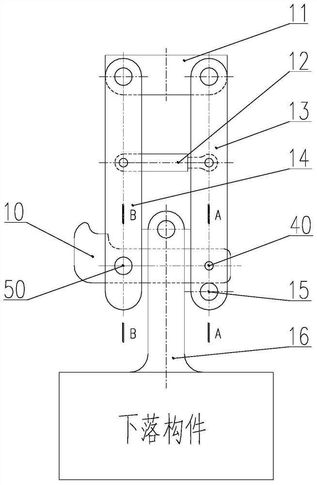
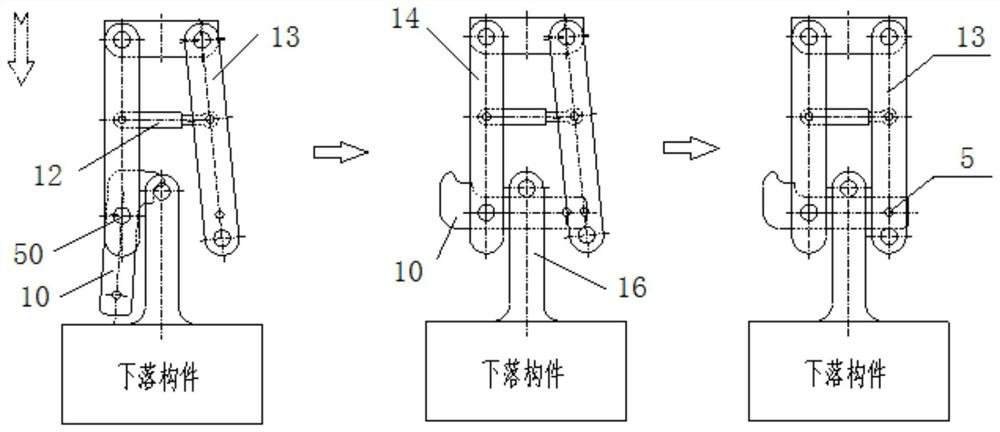
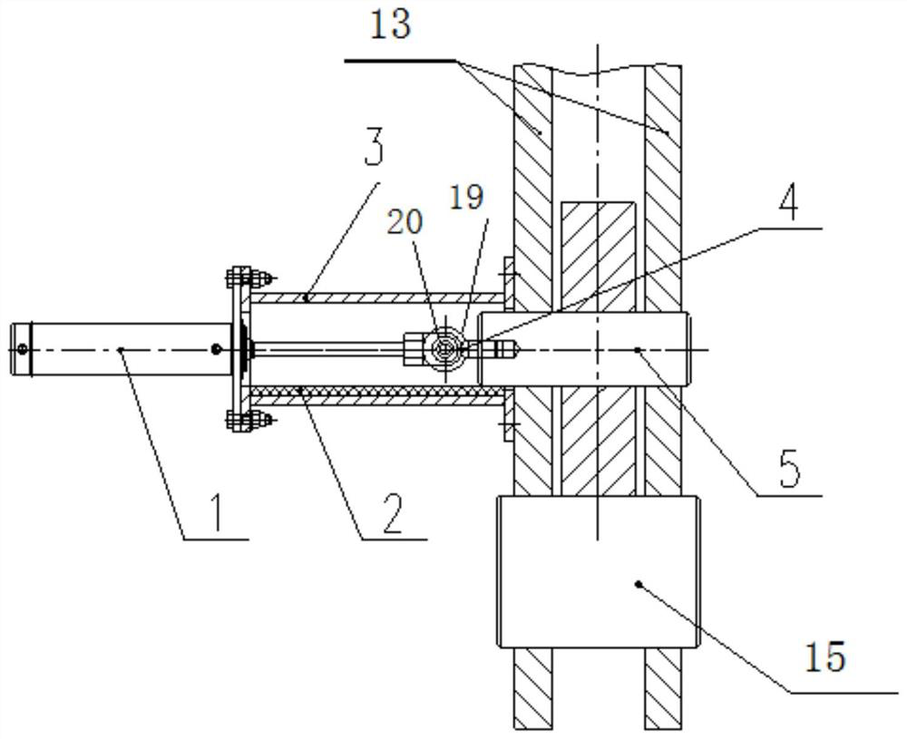
[0038] Such as Figure 1-Figure 8 As shown, a decoupling resetting device of the present invention includes: a safety pin insertion device 40, a swing beam rotation device 50 and a corresponding hydraulic control system, and also includes two front and rear swing arms I13, two front and rear swing arms II 14, There is a fixed ear plate 11 in the middle, and an opening and closing hydraulic cylinder 12 in the middle; the top of the swing arm I13 and the swing arm II 14 are connected together by the fixed ear plate 11 (the front and rear two swing arms I13 and the left end of the fixed ear plate 11 in the middle are connected by a pin The shaft is fixedly connected, and the front and rear two swing arms II14 and the fixed ear plate 11 right ends in the middle are also fixedly connected by pin shafts); the middle part of the swing arm I13 and the swing arm II 14 is respectively connected with the two ends of the opening and closing hydraulic cylinder 12 (the swing arm I13 is fixe...


PUM


Abstract

The invention discloses an unhooking and resetting device. The device comprises a safety pin inserting and pulling device, a swinging cross beam rotating device, a front swing arm I, a rear swing arm I, a front swing arm II, a rear swing arm II, a middle fixed lug plate and an opening and closing hydraulic oil cylinder. The safety pin inserting and pulling device comprises a plug pin hydraulic oil cylinder, a middle flange, a rotating hinge point and a safety pin. The plug pin hydraulic oil cylinder and the safety pin are respectively arranged on two sides of the middle flange and are connected through the rotating hinge point. The swinging cross beam rotating device comprises a hydraulic motor, a transmission shaft, a rotating shaft and a swinging cross beam. The transmission shaft is mounted in a mounting flange. The rotating shaft is mounted on the swing arms II. One end of the transmission shaft is connected with the hydraulic motor and sleeved with a sliding sleeve, and the other end of the transmission shaft extends into a screw hole in the front end of the rotating shaft. The sliding sleeve is in embedded connection with the rotating shaft through trapezoidal teeth on the end surface. The sliding sleeve is connected with a shifting connecting rod. The unhooking and resetting device can be rapidly and reliably unhooked and can be rapidly reset after unhooking, the unhooking and resetting process is simplified, and the test safety is improved.

Description

technical field [0001] The invention belongs to the technical field of free fall test of an elevator test device, and relates to a decoupling reset device used for free fall test of an elevator test tower. Background technique [0002] Unhook reset device (such as figure 1 Shown) is the key actuator for the free fall test of the elevator test tower, connected to the upper guide device ( figure 1 Not shown in ) and the lower part of the test load ( figure 1 The falling member in is the test load). Unhook reset device (such as figure 1 Shown) includes front and rear two swing arms I13, front and rear two swing arms II 14, a fixed ear plate 11 in the middle, an opening and closing hydraulic cylinder 12 in the middle, safety pin 5, swing beam 10, fixed pin 15; I13 and the top of the swing arm II14 are connected together through the fixed ear plate 11; the middle parts of the swing arm I13 and the swing arm II14 are respectively connected with the two ends of the opening and ...

Claims


Application Information

Patent Timeline
Patent Type & Authority Applications(China)
IPC IPC(8): F16B1/04F16B1/02F16B19/02F15B11/16F15B13/06B66B5/00
CPCB66B5/00F15B11/16F15B13/06F16B1/02F16B1/04F16B19/02
Inventor 倪骁宇刘彦飞南海博汤大伟任宇刚李福森强少华程实张军张铮褚悦
Owner ZHONGCHUAN NO 9 DESIGN & RES INST
Why Eureka
Try Eureka