Novel vacuum suction cup lifting appliance

A vacuum suction cup and suction cup technology, applied in the direction of load hanging components, transportation and packaging, etc., can solve the problem that the suction cup cannot perform automatic height and width adjustment material handling, cannot effectively divide the material to be handled, and has no mechanical anti-drop setting. , to achieve efficient and fast handling process, improve handling efficiency, and facilitate stable adsorption.

Pending Publication Date: 2021-10-15
湖南天桥嘉成智能科技有限公司
View PDF1 Cites 0 Cited by
  • Summary
  • Abstract
  • Description
  • Claims
  • Application Information

AI Technical Summary

Problems solved by technology

[0004] Patent No. CN200910074906.7 discloses a double-vacuum suction cup spreader, which can adapt to the handling of materials with uneven surfaces, but it cannot effectively separate the transported materials, and its suction cups cannot automatically adjust the height and width. It is suitable f

Method used


Image

  • Novel vacuum suction cup lifting appliance
  • Novel vacuum suction cup lifting appliance
  • Novel vacuum suction cup lifting appliance

Examples


Embodiment 1

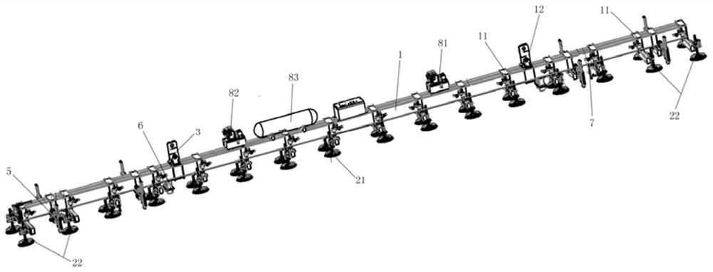
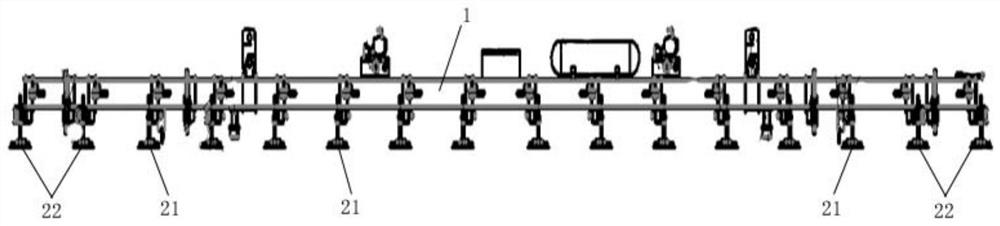
[0035] a kind of like figure 1 The new vacuum suction cup spreader shown is used in metallurgy and heavy industry to carry heavy plates. It is used in conjunction with the crown block, including the frame connected to the crown block. The frame includes the main beam 1, and the length direction of the main beam is A plurality of sets of vacuum suction cup devices 21 and four sets of expansion suction cup devices 22 are arranged through the beam hanger 11. Each of the four sets of expansion suction cup devices 22 is distributed at both ends of the main beam 1 in the length direction, and the vacuum suction cup devices 21 are located at both ends of the main beam. Between the splitting suction cup devices 21 at the end; the splitting suction cup device 22 is mainly used for splitting the sheets, and also for suction and lifting, and the vacuum suction cup device 21 realizes the adsorption and lifting of the sheets. The quantity arrangement on the top is selected according to the...


PUM


Abstract

The invention relates to the technical field of carrying equipment, and discloses a novel vacuum suction cup lifting appliance aiming at the defect that a traditional suction cup lifting appliance cannot realize smooth separation. The novel vacuum suction cup lifting appliance comprises a rack connected with a crown block; the rack comprises a main beam; at least one group of vacuum suction cup devices and at least one group of separation suction cup devices are arranged in the length direction of the main beam through cross beam hanging pieces; each group of vacuum suction cup devices comprises at least two common suction cup structures which are uniformly distributed in the width direction of the main beam; each group of separation suction cup devices comprises at least two separation suction cup structures which are uniformly distributed in the width direction of the main beam; each common suction cup structure and each separation suction cup structure are each provided with a suction cup lifting device capable of independently controlling the suction cups to move up and down; and the separation suction cup devices are arranged close to the end of the main beam. The arrangement of the separation suction cup devices is added; meanwhile, each suction cup structure is independently provided with one suction cup lifting device; separation operation of a plurality of overlapped plates can be rapidly achieved; and the carrying operation efficiency is improved.

Description

technical field [0001] The invention relates to the technical field of handling equipment design, in particular to a novel vacuum suction cup spreader suitable for large-area material handling. Background technique [0002] In the field of metallurgy and heavy industry, it generally involves large-scale material handling, such as cutting machine blanking production line, which needs to transport the entire steel plate to the cutting machine platform, but at present, it is generally lifted manually. Manual lifting steel plate is not only The danger is great, and labor intensity is big, and work efficiency is low. The traditional electromagnetic lifting tool is easy to penetrate the magnetic field when lifting the thin steel plate, which is not conducive to the separation of the steel plate. [0003] With the development of industrial automation and intelligence, the heavy industry is also paying more and more attention to the construction of automated production lines. Heavy...

Claims


Application Information

Patent Timeline
IPC IPC(8): B66C1/02
CPCB66C1/0218B66C1/025B66C1/0256
Inventor 郭思明侯延壮毛轩昂查铂郑祎
Owner 湖南天桥嘉成智能科技有限公司
Why Eureka
Try Eureka