A non-isolated inverter for suppressing ripple and its control method

A control method and isolation technology, applied in control/regulating systems, instruments, regulating electrical variables, etc., can solve the problems of large inductance and capacitance, poor practicability, complex control algorithms, etc., to suppress low-frequency current ripple, extend Service life, the effect of small decoupling capacitance

Active Publication Date: 2019-03-01
NANJING UNIV OF AERONAUTICS & ASTRONAUTICS
View PDF3 Cites 0 Cited by
  • Summary
  • Abstract
  • Description
  • Claims
  • Application Information

AI Technical Summary

Problems solved by technology

Fukushima K, Norigoe I, Shoyama M, et al, "Input current-ripple consideration for the pulse-link DC-AC converter for fuel cells by small series LC circuit", Proceedings of IEEE 24thAnnual Applied Power Electronics Conference and Exposition, 2009: 447 -451 proposes a solution by adding an LC series resonant circuit and designing its resonant frequency to twice the output frequency, as shown in the attached figure 1 As shown, the current ripple on the DC input side is effectively suppressed, but the required inductance and capacitance values ​​are relatively large, the power density and service life of the system are affected, and the practicability is poor.
Kwon J, Kim E, Kwon B, Nam K, "High-Efficiency FuelCell Power Conditioning System With Input Current Ripple Reduction", IEEE Transaction on Industry Electronics, 2009, 56(3): 826-834 Using multi-objective control ideas and power electronics The high-frequency control characteristics of the converter, through the real-time calculation of the duty cycle of the main switch tube, realizes the input-output voltage conversion and the suppression of the input-side current ripple, which can improve the utilization rate of the fuel cell. figure 2 shown, but this scheme requires high control precision and real-time performance, and the control algorithm is complex

Method used


Image

  • A non-isolated inverter for suppressing ripple and its control method
  • A non-isolated inverter for suppressing ripple and its control method
  • A non-isolated inverter for suppressing ripple and its control method

Examples


Embodiment Construction

[0034] Below in conjunction with accompanying drawing, the technical scheme of invention is described in detail:

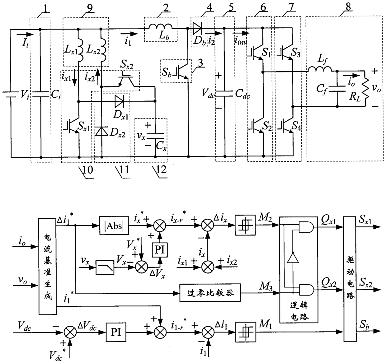
[0035] attached image 3 It is a structural schematic diagram of a main circuit of a non-isolated inverter for suppressing ripple and its control method. by the DC power supply V i , input capacitor 1, boost inductor 2, main switch tube 3, freewheeling diode 4, intermediate DC bus capacitor 5, two inverter bridge arms 6 and 7, filter circuit 8, auxiliary inductor 9, auxiliary switch tube 10, auxiliary Composed of diode 11 and auxiliary capacitor 12. C i is the input capacitance, L b is the boost inductor, L x1 , L x2 is the auxiliary inductance, D x1 、D x2 is the auxiliary diode, S x1 , S x2 is the auxiliary switch tube, S b is the main switching tube, D b is the freewheeling diode, C x is the auxiliary capacitor, C dc is the intermediate DC bus capacitance, S 1 ~S 4 is the power switch tube, L f is the output filter inductor, C f is the output f...


PUM


Abstract

The invention discloses a non-isolated inverter for suppressing ripples and a control method thereof, comprising a DC power supply, an input capacitor, a boost inductor, a main switch tube, an auxiliary inductor, an auxiliary switch tube, an auxiliary diode, an auxiliary capacitor, and The current diode, the intermediate DC bus capacitor, the first inverter bridge arm, the second inverter bridge arm and the filter circuit; the control method is: the output voltage sampling value and the output current sampling value input current reference generation circuit to obtain the current reference, and the inductor current The sampled value and current reference pass through the subtractor, current controller, logic circuit, and drive circuit to control the inductor current to track its reference. The invention adds an auxiliary circuit composed of an auxiliary switch tube, an auxiliary diode and an auxiliary capacitor to the Boost direct-to-direct conversion link of the inverter, and controls the auxiliary current to track its reference, thereby effectively suppressing the low-frequency ripple of the input current.

Description

technical field [0001] The invention relates to a non-isolated inverter for suppressing ripples and a control method thereof, which belongs to non-isolated, medium and high-power inverters, and uses an added auxiliary circuit to suppress low-frequency ripples of input current. Background technique [0002] In new energy and other distributed power generation systems, in order to obtain the high-voltage AC power required by the load, the inverter generally adopts a two-stage structure, that is, the front stage is a DC converter for boosting and stabilizing functions, and the latter stage is a single inverter. phase inverter. For this kind of system, the power pulsation component of twice the output frequency contained in the output power is fed back to the DC input side as low-frequency current ripple, which affects the service life of input sources such as batteries and fuel cells, and reduces the efficiency of the system. Therefore, the low-frequency current ripple in the ...

Claims


Application Information

Patent Timeline
Patent Type & Authority Patents(China)
IPC IPC(8): H02M7/5387H02M3/335H02M1/14
CPCH02M1/14H02M3/335H02M7/4826H02M7/5387H02M7/539H02M1/007
Inventor 陈仲袁涛李梦南
Owner NANJING UNIV OF AERONAUTICS & ASTRONAUTICS
Why Eureka
Try Eureka