
RR frame filtering method and system

A frame filtering and filtering module technology, applied in the field of communication, can solve problems such as affecting the running speed of the receiving end

Inactive Publication Date: 2017-05-10
GENEW TECH
View PDF3 Cites 0 Cited by
  • Summary
  • Abstract
  • Description
  • Claims
  • Application Information

AI Technical Summary

Problems solved by technology

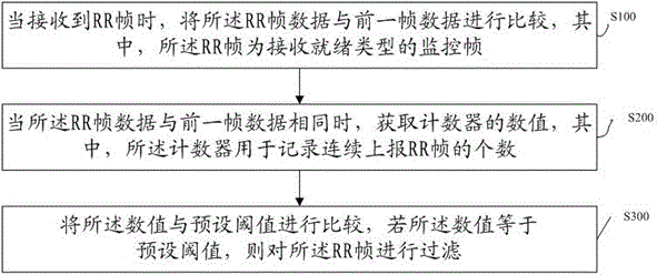
[0004] The technical problem to be solved by the present invention is to provide a RR frame filtering method and system for the deficiencies in the prior art, so as to solve the problem that the existing receiving end receives a large number of identical RR frames and submits them to the upper layer software for processing, so as to cause system duplication at the receiving end The problem of processing and responding to redundant messages that affects the speed of the receiving end

Method used


Image

  • RR frame filtering method and system
  • RR frame filtering method and system
  • RR frame filtering method and system

Examples


Embodiment 1

[0067] In this example, if figure 2 As shown, the RR frame filtering method is based on pre-setting a state machine used to indicate the number of RR frames received by the connection. Wherein, the states of the state machine are 0 state, 1 state and 2 state respectively; the 0 state indicates that an RR frame has not been received, the 1 state indicates that one RR frame is received, and the 2 state indicates that a RR frame is received continuously 2 RR frames; the method specifically includes:

[0068] H10. Receive the frame sent by the network side device, and obtain the length of the frame;

[0069] H20. Comparing the length of the frame with the preset length, if consistent, execute step H30; if inconsistent, execute step H110;

[0070] H30, comparing the data of the frame with the data of the previous frame, if they are the same, execute step H40, if not, save the frame data and execute step H100;

[0071] H40. Obtain the difference between the frame receiving time a...


PUM


Abstract

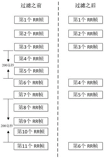
The invention discloses an RR frame filtering method and system. The method comprises the following steps: when receiving an RR frame, comparing the RR frame data with previous frame data, wherein the RR frame is a reception-ready-type supervisory frame; when the RR frame data is same with the previous frame data, obtaining a value of a counter, wherein the counter is used for recording the number of continuously-received RR frames; and comparing the value with a preset threshold value, and if the value is equal to the preset threshold value, carrying out filtering on the RR frames. By carrying out filtering on the same RR frames received by a driving layer, the problem that when an existing receiving end receives a lot of same RR frames and submits the RR frames to upper software for processing, operation speed of the receiving end is influenced due to repeated processing and redundant information response of a system of the receiving end is solved.

Description

technical field [0001] The present invention relates to the field of communication technology, in particular to an RR frame filtering method and system. Background technique [0002] The RR (receiver ready) frame is a receiving ready monitoring frame specified in the LAPD protocol (used for the link layer protocol on the Abis interface between the BTS and the BSC), and is mainly used to indicate that the receiving end is ready to receive a The IDLE frame and the RR frame can also confirm the previously received frame. The LAPD protocol is defined in the second layer of the OSI7-layer model according to the ISDN (Integrated Services Digital Network, Integrated Services Digital Network) protocol. Wherein, the ISDN protocol stack corresponds to the 3 layers of the OSI7 layer model, and defines the interface type of BRI / PRI at the physical layer; defines the LAPD protocol on the D channel according to the ISDN channel definition at the second layer; on the third layer The sign...

Claims


Application Information

Patent Timeline
Patent Type & Authority Applications(China)
IPC IPC(8): H04L12/26
CPCH04L43/028H04L43/16
Inventor 闭梁祖
Owner GENEW TECH
Learn More