This helps you quickly interpret patents by identifying the three key elements:
Problems solved by technology
Method used
Benefits of technology
Problems solved by technology
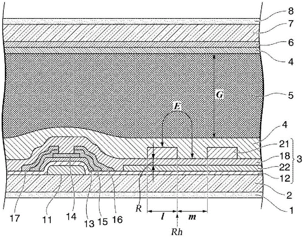
The magnitude of the potential difference gradient caused by the distance between electrodes has a great influence on the design of the display element, and there is no understanding of issues such as burn-in and drop marks that are difficult to predict from conventional technologies.
Method used
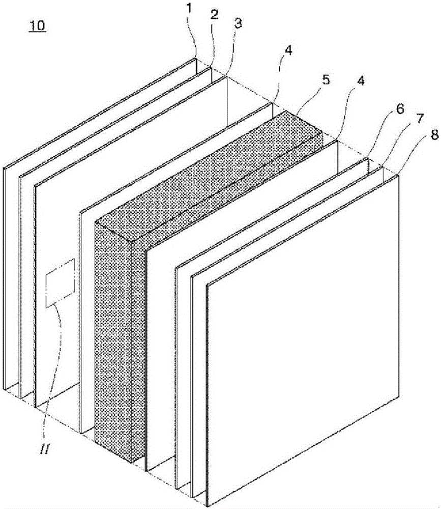
Image
Click on the blue label to locate the original text in one second.
Reading with bidirectional positioning of images and text.
Examples
Embodiment 1
[0258] (Example 1 (Liquid Crystal Composition 1) and Comparative Example 1)
[0259] A liquid crystal composition (liquid crystal composition 1) having the composition shown below was prepared, and its physical property values were measured. The results are shown in the table below.
[0260] Furthermore, the prepared liquid crystal composition 1 was poured into the said liquid crystal display element, and the evaluation of various physical property values and display characteristics was performed.
[0261] Simultaneously, the liquid crystal composition of Comparative Example 1 having a different structure from the liquid crystal composition specified in the present invention was prepared, and a liquid crystal display element was fabricated and evaluated in the same manner.
[0262] In addition, the symbol on the left side of the content is the description of the abbreviation of the said compound.
[0263] [chem 30]
[0264] Example 1
[0265]
[0266] [chem 31]
Embodiment 2
[0273] (Example 2 (Liquid Crystal Composition 2) and Comparative Example 2)
[0274] A liquid crystal composition (liquid crystal composition 2) having the composition shown below and the liquid crystal composition of Comparative Example 1 were prepared, and an FFS mode liquid crystal display element was prepared in the same manner, and its physical properties were measured. The results are shown in the table below.
[0275] Simultaneously, the liquid crystal composition of Comparative Example 2 having a different structure from the liquid crystal composition specified in the present invention was prepared, and a liquid crystal display element was fabricated and evaluated in the same manner.
[0276] [Table 2]
[0277] Sample name Example 2 Comparative example 2 T NI / ℃
86.5 89.7 Δn 0.110 0.088 Δε -3.90 -3.32 n / mPa·s 22.0 21.0 gamma 1 / mPa·s
144 162 gamma 1 / Δn 2
11.9 20.9 gamma 1 / Δn 2 / |Δε|
3.05 ...
Embodiment 3 to 8
[0281] The liquid crystal compositions of Examples 3 to 8 having the compositions shown below were prepared, and an FFS mode display element was produced in the same manner, and its physical property values were measured. The results are shown in the table below.
[0282] [table 3]
[0283] Sample name Example 3 Example 4 Example 5 Example 6 Example 7 Example 8 T NI / ℃
[0284] It can be seen that the liquid crystal display elements of Examples 3 to 8 also have characteristics practical as liquid crystal TVs, and flicker characteristic to the FFS mode is effectively reduced.
PUM
Property
Measurement
Unit
superconducting critical temperature
aaaaa
aaaaa
phase transition temperature
aaaaa
aaaaa
electrical resistivity
aaaaa
aaaaa
Abstract
A dispenser (100) comprises a bottle (110) having an external wall (111), a gasket (120) defining an upper cavity(112) and a lower cavity(114) within the bottle and configured to substantially seal said upper cavity (112) form said lower cavity (114), and a fluid dispensing mechanism configured to allow fluid to be dispensed from said lower cavity (114) to the outside of the bottle (110) when the dispensing mechanism is actuated, wherein said gasket (120) is capable of moving towards the lower cavity (114) upon actuation of the dispensing mechanism and of moving towards the upper cavity (112) upon entrance of the fluid into said lower cavity (114), and a fluid refill mechanism configured to allow fluid to enter said lower cavity (114) when said refill mechanism is fluidly coupled to a fluid source.
Application Information
Patent Timeline
Application Date:The date an application was filed.
Publication Date:The date a patent or application was officially published.
First Publication Date:The earliest publication date of a patent with the same application number.
Issue Date:Publication date of the patent grant document.
PCT Entry Date:The Entry date of PCT National Phase.
Estimated Expiry Date:The statutory expiry date of a patent right according to the Patent Law, and it is the longest term of protection that the patent right can achieve without the termination of the patent right due to other reasons(Term extension factor has been taken into account ).
Invalid Date:Actual expiry date is based on effective date or publication date of legal transaction data of invalid patent.
