Supercharge Your Innovation With Domain-Expert AI Agents!

Payment device cycle print test structure and test method

A technology for payment equipment and testing structures, applied in printing devices, printing, etc., can solve the problems of large printing paper consumption, waste of manpower and material resources, and low efficiency, and achieve the effect of not wasting paper, improving efficiency, and liberating human resources

Active Publication Date: 2019-02-22
福建瑞之付微电子有限公司
View PDF11 Cites 0 Cited by
  • Summary
  • Abstract
  • Description
  • Claims
  • Application Information

AI Technical Summary

Problems solved by technology

[0002] Existing payment terminals will inevitably consume a large amount of printing paper during the test process. Currently, some stress tests that do not require the quality of the printed content (such as: printer overheating abnormal return value test, battery endurance test under continuous printing state, etc.) ) process, new printing paper is often used for one-time printing, and the amount of paper loaded at one time is limited. During the pressure process, new paper needs to be interrupted, and manpower duties need to be arranged, which is inefficient and wastes manpower and material resources.

Method used


Image

  • Payment device cycle print test structure and test method
  • Payment device cycle print test structure and test method
  • Payment device cycle print test structure and test method

Examples


Embodiment Construction

[0019] The present invention will be described in further detail below in conjunction with the accompanying drawings and specific embodiments.

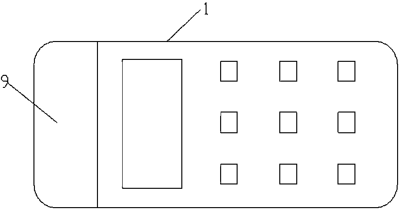
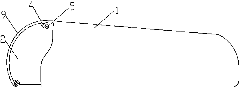
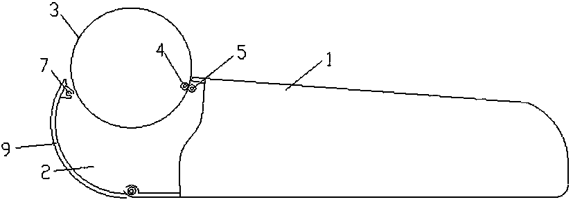
[0020] The circulation printing test structure of the payment device of the present invention includes a body 1 and a paper slot 2 arranged in the body 1 for holding printing paper, and a printing head and a detachable printer located at the side of the printing head are arranged on the side of the paper slot 2. The reel 4 and the fixed reel 5, the detachable print reel 4 and the fixed reel 5 rotate against each other, the end of the detachable print reel is provided with a first meshing gear 6, and the body 1 is provided with a first meshing gear Mesh and rotate the second meshing gear 8, the second meshing gear 8 can be driven by a motor to rotate, or driven by other intermediate gears, the detachable printing reel is installed on the openable cover 9, the machine One side of the cover 9 is hinged on the body, and the body 1 is prov...


PUM


Abstract

The invention relates to a circulation printing test structure and test method of paying equipment. The circulation printing test structure is characterized by comprising a machine body and a paper groove formed in the machine body and used for placing printing paper; the side of the paper groove is provided with a printing head, a detachable printing scroll and a fixed scroll, wherein the detachable printing scroll and the fixed scroll are located on the side of the printing head; a first meshing gear is arranged at the end of the detachable printing scroll; a second meshing gear used for rotating with the first meshing gear in a meshing mode is arranged in the machine body; the second meshing gear is driven by a motor to rotate; the detachable printing scroll is mounted on a machine cover which can be opened and closed; one side of the machine cover is hinged to the machine body; and buckle grooves capable of dismounting and assembling the detachable printing scroll are formed in the place, located on the side of the second meshing gear, of the machine body. By using the circulation paper, cyclic utilization of the paper can be achieved, and waste of the paper does not occur. When certain pressure tests which do not require the printing content quality (for example, a printing machine overheating abnormal returning value test and a cruising ability test of batteries in the state of continuous printing) are conducted, breaking off to add new paper is not needed, efficiency can be improved, people participation is not needed, the manpower resource is free, the automated test requirements are met, and a pressure test can be executed for a long time.

Description

Technical field: [0001] The invention relates to a payment device cycle printing test structure and test method. Background technique: [0002] Existing payment terminals will inevitably consume a large amount of printing paper during the test process. Currently, some stress tests that do not require the quality of the printed content (such as: printer overheating abnormal return value test, battery endurance test under continuous printing state, etc.) ) process, new printing paper is often used for one-time printing, and the amount of paper loaded at one time is limited. During the pressure process, it is necessary to stop adding new paper, and it is necessary to arrange manpower duties, which is inefficient and wastes manpower and material resources. Invention content: [0003] The object of the present invention is to provide a payment device cyclic printing test structure and testing method, the payment device cyclic printing testing structure and testing method are re...

Claims


Application Information

Patent Timeline
Patent Type & Authority Patents(China)
IPC IPC(8): B41J15/04
CPCB41J15/04B41J15/042
Inventor 徐昊高锵陈良毅
Owner 福建瑞之付微电子有限公司
Features
  • R&D
  • Intellectual Property
  • Life Sciences
  • Materials
  • Tech Scout
  • Unparalleled Data Quality
  • Higher Quality Content
  • 60% Fewer Hallucinations
Learn More