Control circuit of vehicle alert trigger mode

A trigger method and control circuit technology, applied in vehicle parts, locomotives, brakes, etc., can solve the problem of not receiving traction commands, and achieve the effect of reducing the use of relays, enriching functions, and reducing failure rates.

Active Publication Date: 2017-05-17
ZHUZHOU ELECTRIC LOCOMOTIVE CO
View PDF5 Cites 6 Cited by
  • Summary
  • Abstract
  • Description
  • Claims
  • Application Information

AI Technical Summary

Problems solved by technology

[0005] When the driver releases the alert button, the KM1 contact of the delayed disconnection relay will not be disconnected within a certain period

Method used


Image

  • Control circuit of vehicle alert trigger mode
  • Control circuit of vehicle alert trigger mode
  • Control circuit of vehicle alert trigger mode

Examples


Embodiment Construction

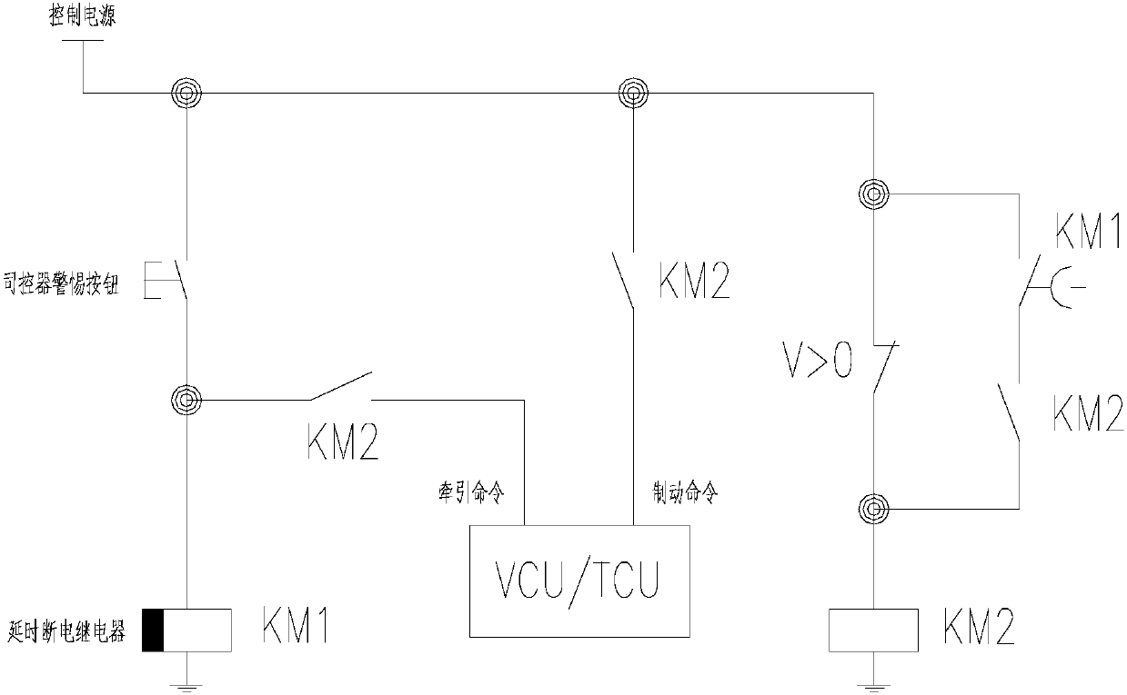
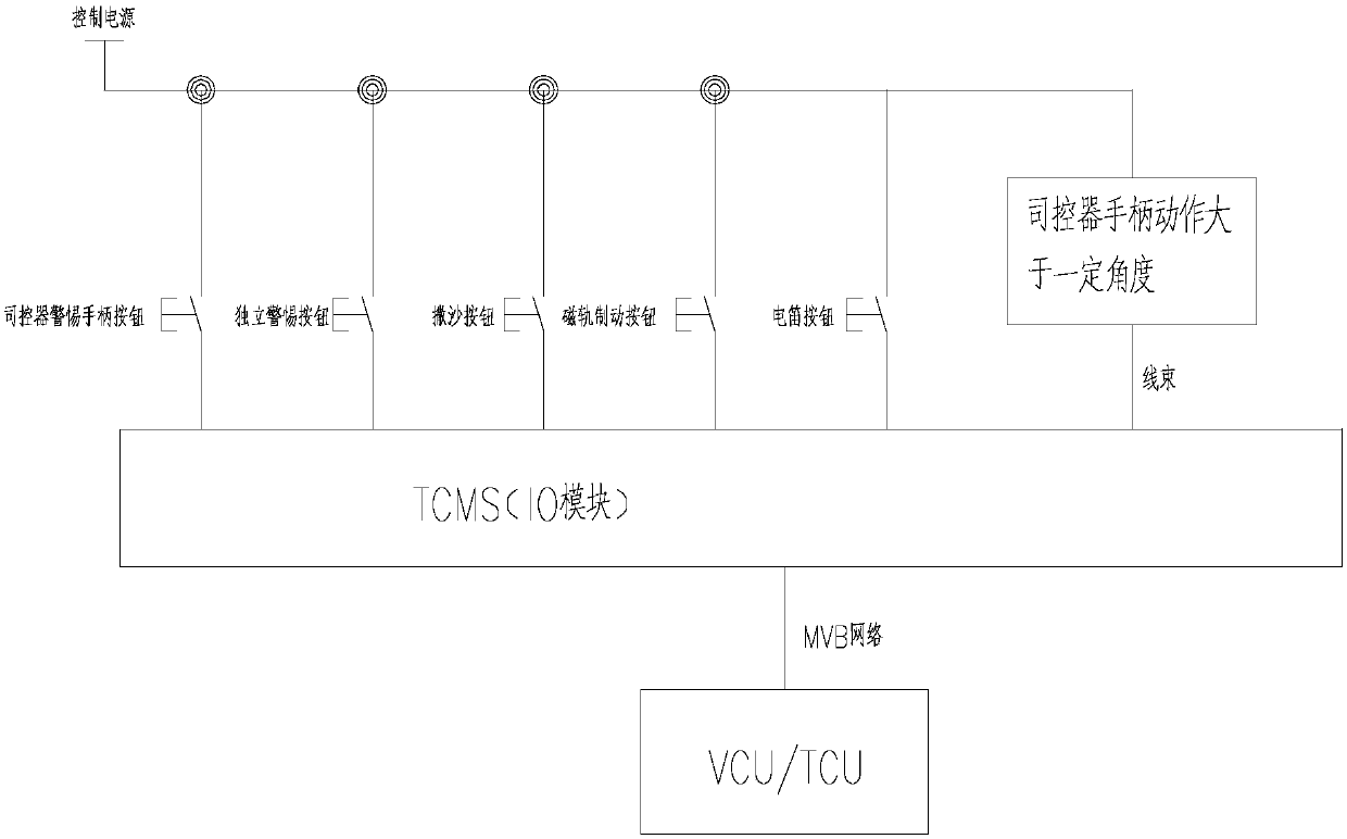
[0013] The present invention will cancel the delay disconnection relay and the self-holding circuit of KM2, the function of the above-mentioned original circuit will be collected by the IO module of TCMS and through its initial arrangement, finally sent to VCU / TCU by MVB train network, by VCU / TCU Form the logic of traction, braking command and self-locking. In addition, the VCU / TCU can also determine the duration of the brake trigger when the alert button is released according to the speed signal transmitted by the speed sensor. When the train is at 50KM / h, release the vehicle for 5 seconds and apply the brakes.

[0014] The vigilance system logic of the present invention is described as follows:

[0015] Considering the mixed running of low-floor vehicles and social vehicles, full manual driving, etc., the range of alert buttons is expanded from only using the controller handle alert button to: using the controller handle button, using additional alert buttons, and sanding b...


PUM


Abstract

The invention discloses a control circuit of a vehicle alert trigger mode. The control circuit comprises a control source. The control source is connected with a driver controller alert handle switch, an independent alert switch, a sand spreading switch, a magnetic track brake switch and an electric whistle switch. The driver controller alert handle switch, the independent alert switch, the sand spreading switch, the magnetic track brake switch, the electric whistle switch and a driver controller handle are all connected into a TCMS module. The TCMS module is in communication with a VCU/TCU.

Description

technical field [0001] The invention relates to the field of vehicle circuit control circuits, in particular to a control circuit of a vehicle vigilance trigger mode. Background technique [0002] In the prior art, the driver's alert button usually adopts the self-resetting button on the main handle of the controller, and the timing of the alert button generally adopts a time relay. Once the driver releases the vigilance button for a certain period of time, the vehicle will trigger the brake. After the brake is triggered, the vehicle must wait until the vehicle stops before the brake can be canceled and the vehicle can be towed again. Such as figure 1 shown. [0003] figure 1 The specific working process: when the driver presses the alert button, the delay power-off relay KM1 is energized and closed. When the vehicle is not started (0 speed), the KM2 relay will be energized. The contacts of KM1 and its own contacts form a self-holding circuit, and on the other hand, the ...

Claims


Application Information

Patent Timeline
IPC IPC(8): B60T7/12B61C17/00
CPCB60T7/128B61C17/00
Inventor 司尚卓张宇尚江傲陈小康雷张文胡禹峰林建鹯
Owner ZHUZHOU ELECTRIC LOCOMOTIVE CO
Why Eureka
Try Eureka