
Integrated multistage axial flow contrarotating turbine structure

A counter-rotating turbine, integrated technology, applied in the direction of non-variable engines, blade support components, engine components, etc., can solve the problems of multiple stages and large volume of turbines

Active Publication Date: 2017-05-17
XI AN JIAOTONG UNIV
View PDF5 Cites 1 Cited by
  • Summary
  • Abstract
  • Description
  • Claims
  • Application Information

AI Technical Summary

Problems solved by technology

In this process, since the guide vane does not participate in the rotation, the single-stage enthalpy drop of the turbine is small, resulting in more turbine stages and larger volume

Method used


Image

  • Integrated multistage axial flow contrarotating turbine structure
  • Integrated multistage axial flow contrarotating turbine structure
  • Integrated multistage axial flow contrarotating turbine structure

Examples


Embodiment Construction

[0021] The present invention will be further described in detail below in conjunction with the accompanying drawings.

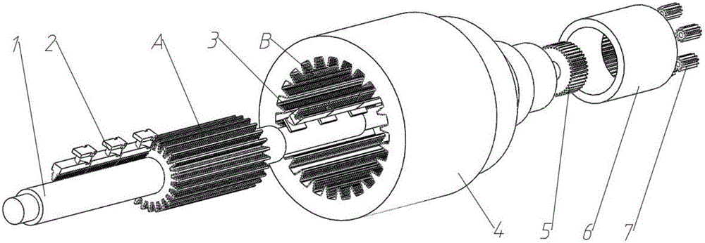
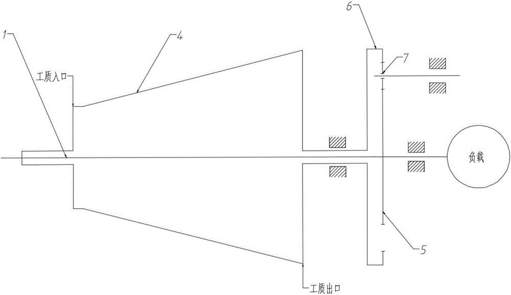
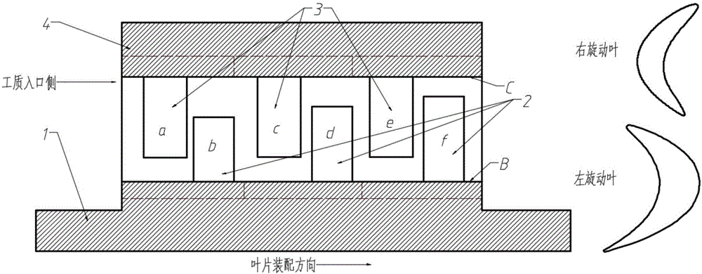
[0022] see figure 1 As described above, the present invention is a multi-stage integral axial-flow counter-rotating turbine structure, comprising: an inner rotor 1, an outer rotor 4, a sun gear 5, an outer ring gear 6 and a planetary carrier 7; the outer circumference of the inner rotor 1 is provided with several rows The left-handed blade slots A extending in the axial direction, the blade roots of several rows of left-handed blades are stuck in the corresponding left-handed blade slots A; the inner wall of the outer rotor 4 is provided with several rows of right-handed blade slots extending in the axial direction B, the blade roots of several rows of right-rotating blades are stuck in the corresponding right-rotating blade slots B.

[0023] The inner rotor 1, the left-handed rotor blades 2, the right-handed rotor blades 3 and the outer rotor 4 constitute t...


PUM


Abstract

The invention discloses an integrated multistage axial flow contrarotating turbine structure which comprises an inner rotor, an outer rotor, a sun gear, an outer gear ring and a planet carrier. The outer rotor is arranged on the periphery of the inner rotor. The inner rotor and the sun gear are arranged coaxially and fixedly connected. The outer rotor and the outer gear ring are coaxial and fixedly connected. The sun gear and the planet carrier are arranged in the outer gear ring. The outer gear ring is engaged with the sun gear through a plurality of planet gears on the planet carrier. By arranging the outer rotor provided with a right rotating blade on the inner rotor provided with a left rotating blade in an opposite installing angle in a sleeving mode, high-temperature working media can be made to push the inner rotor and the outer rotor to rotate when flowing into a turbine, and two strands of power are synthesized to be output through the planet gears. By adoption of the novel integrated multistage axial flow contrarotating turbine structure, the turbine single-stage working capability is enhanced, and the size of the turbine is decreased; and power output structures of the planet gears can be adjusted so as to be matched with the optima speed ratios of all stages of the turbine, and accordingly the turbine circumference efficiency of the turbine is improved.

Description

technical field [0001] The invention relates to the field of axial-flow motive turbine machinery, in particular to a multi-stage integral axial-flow counter-rotating turbine structure. Background technique [0002] Compared with reciprocating prime movers, steam turbines and gas turbines, as axial flow prime movers, can generate higher power and have higher thermal efficiency due to the continuous high-speed flow of their working medium in their flow parts, and are widely used in Military and civilian fields such as power generation, distributed energy, ship power and chariot power. [0003] For the current steam turbine and gas turbine, after the high-temperature working fluid enters the turbine, it expands in the guide vane flow channel and obtains a high speed, and then converts the energy of the working fluid into the work of the turbine through the moving blade to drive the rotor to rotate. In this process, since the guide vane does not participate in the rotation, the...

Claims


Application Information

Patent Timeline
Patent Type & Authority Applications(China)
IPC IPC(8): F01D1/26F01D5/06
CPCF01D1/26F01D5/06F05D2240/20
Inventor 张荻郭鼎谢永慧姜伟
Owner XI AN JIAOTONG UNIV
Learn More