Particle filter for motor vehicle

一种颗粒过滤器、机动车辆的技术,应用在分散颗粒过滤、机器/发动机、机械设备等方向,能够解决窄频谱等问题,达到低成本生产的效果

Active Publication Date: 2017-05-17
DR ING H C F PORSCHE AG
View PDF8 Cites 0 Cited by
  • Summary
  • Abstract
  • Description
  • Claims
  • Application Information

AI Technical Summary

Problems solved by technology

In the case of a particle filter according to the prior art as a low-pass filter, this means that it has a narrow frequency spectrum, since relatively high and high frequencies are filtered out and thus no longer audible

Method used


Image

  • Particle filter for motor vehicle
  • Particle filter for motor vehicle

Examples


Embodiment Construction

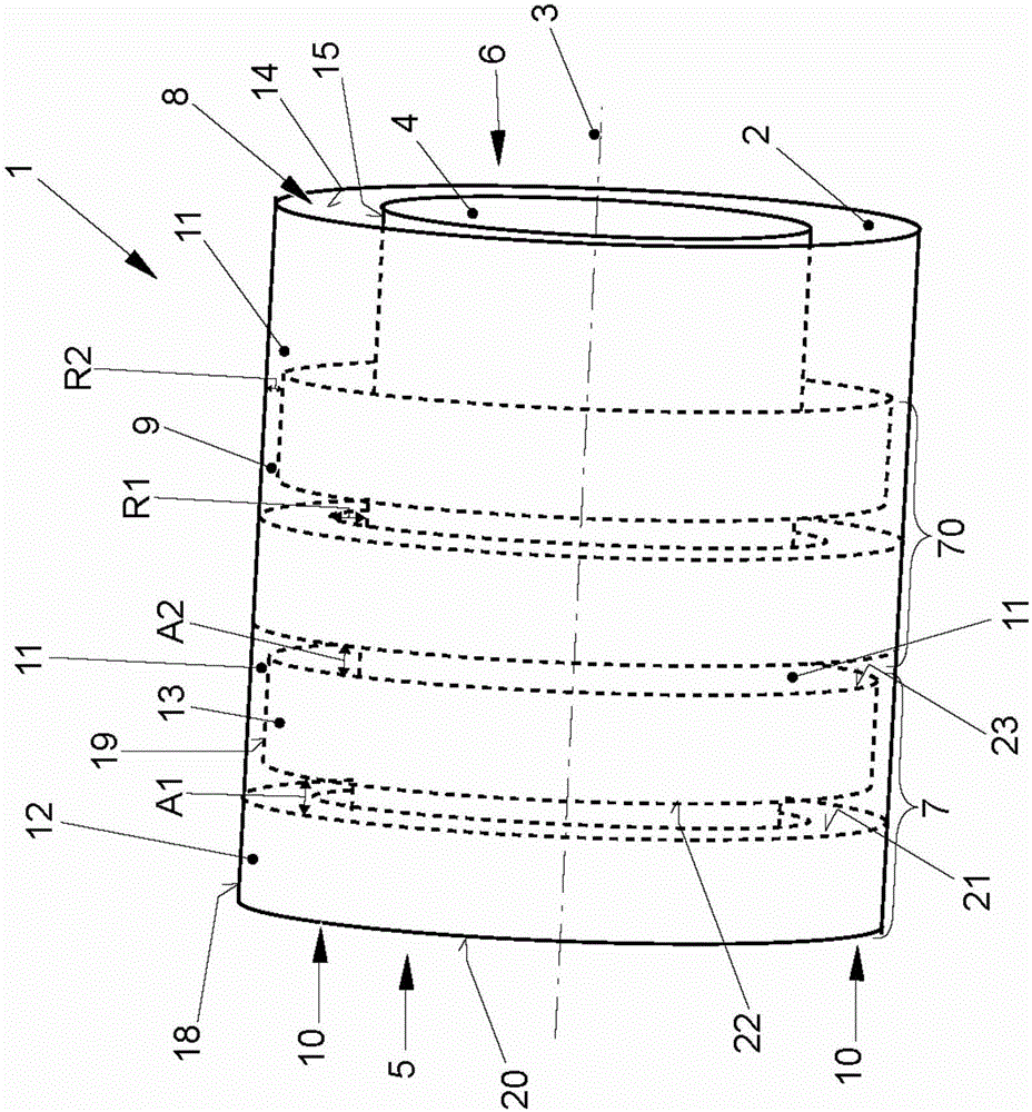
[0022] A particle filter 1 according to the invention for a motor vehicle (not specifically shown) is based on figure 1 designed. The particle filter 1 is arranged in a flow-through exhaust line (not specifically shown) of a motor vehicle, wherein the exhaust line is connected to a motor vehicle internal combustion engine (not specifically shown), so that the exhaust gas of the internal combustion engine can flow through the exhaust line.

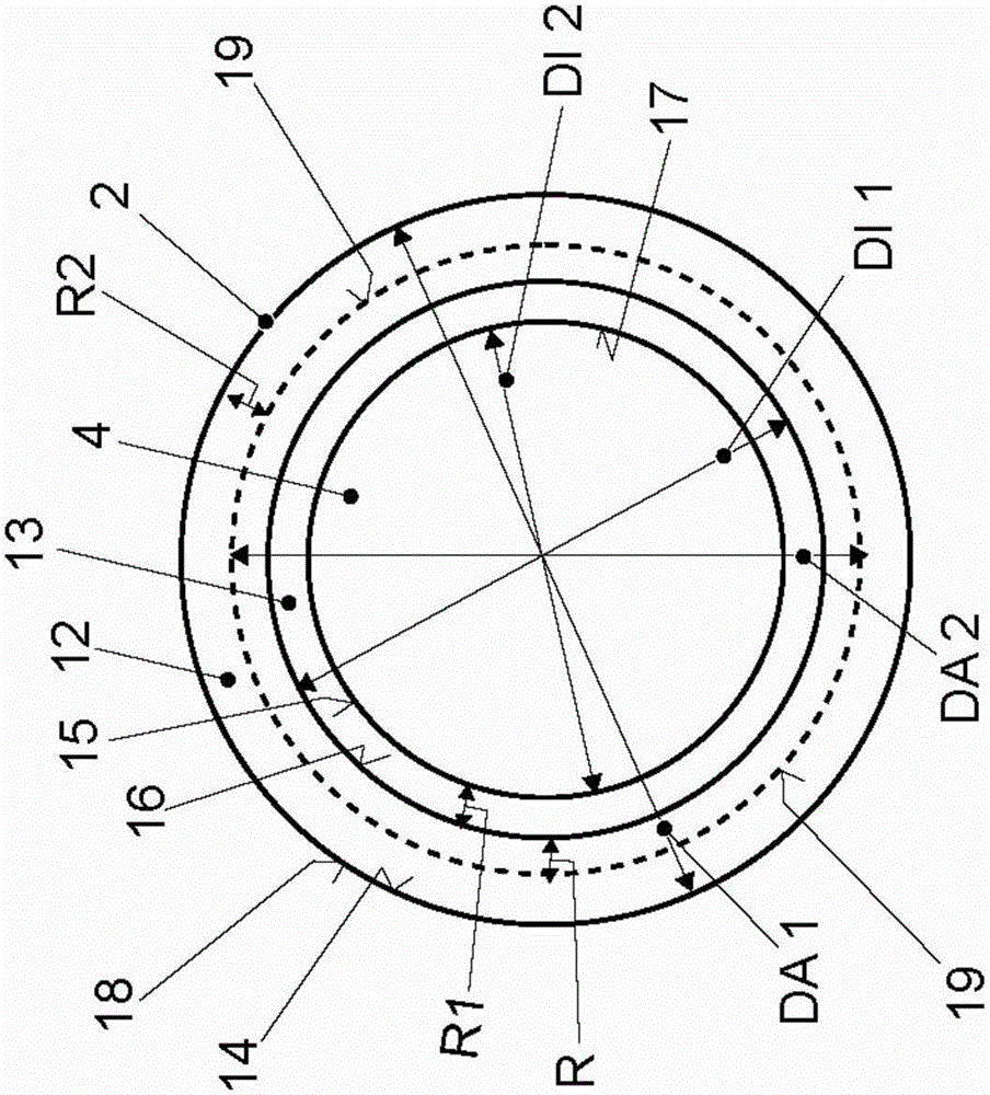
[0023] The particle filter 1 is designed to reduce the emissions of the internal combustion engine, in particular particles or soot. The particle filter has a housing 2 with a longitudinal axis 3 and a core 4 which is accommodated in the housing 2 and allows throughflow.

[0024] The through-flow core 4 is designed in a "monolithic" form, which core is made of ceramic material. This whole 4 has a plurality of flow ducts (not specifically shown) designed to extend in the direction of the longitudinal axis 3 from the inlet region 5 of the ...


PUM


Abstract

A particulate filter for a motor vehicle has a casing (2) that allows through flow. A core (4) is accommodated in the casing (2) and allows through flow. The casing (2) has a longitudinal axis (3). A through flow duct (9) is formed between the casing (2) and the core (4) to allow the through flow of exhaust gas from an internal combustion engine of the motor vehicle. A ring (7) is arranged in the through flow duct (9) and gives the through flow duct (9) a labyrinth-type configuration.

Description

technical field [0001] The invention relates to a particle filter for a motor vehicle according to the preamble of patent claim 1 . Background technique [0002] Particulate filters for motor vehicles are known. Originally, particulate filters were developed to reduce particulate or soot emissions from motor vehicles with diesel engines. Particulate or soot emissions depend on combustion processes in internal combustion engines or internal combustion engines, during which they are also used to reduce emissions from gasoline engines. [0003] Due to its location in the exhaust tract of the internal combustion engine, the particle filter influences the characteristic exhaust sound of the engine of the motor vehicle. Basically, they act as a low pass filter, where higher frequencies are filtered out. That is, the high frequencies of the exhaust noise are attenuated, thereby changing the original sound signature of the motor vehicle. Particle filters according to the prior a...

Claims


Application Information

Patent Timeline
Patent Type & Authority Applications(China)
IPC IPC(8): F01N3/021F01N13/00
CPCF01N3/021F01N13/001F01N2340/00F01N2470/00B01D46/4236F01N1/083F01N3/0222F01N3/0335F01N2470/08Y02T10/12
Inventor L·亨斯勒
Owner DR ING H C F PORSCHE AG
Why Eureka
Try Eureka