Wire winding device of relay, relay comprising same, and mounting method of wire winding device of relay

A technology of winding device and installation method, which is applied in the direction of relays, electromagnetic relays, detailed information of electromagnetic relays, etc., can solve the problems of bruising the paint layer and reducing the surface smoothness of winding coils, etc., and achieves convenient installation, simple structure, and avoids naked effect

Inactive Publication Date: 2017-05-17
宁波金海电子有限公司
View PDF4 Cites 4 Cited by
  • Summary
  • Abstract
  • Description
  • Claims
  • Application Information

AI Technical Summary

Problems solved by technology

[0002] In the production of traditional relays, the coil frame is an indispensable part of the electromagnetic relay. The winding assembly is formed after the coil frame is wound with enameled wire and the corresponding plug-in chip is assembled. The original coil frame structure starts from a section when winding. When it is exposed on the end face of the coil frame, the thread needle constantly collides with the end face and the starting line every time the wire is routed, there is a certain risk of damaging the paint layer, and due to the accumulation of tolerances, the flatness of the winding coil surface is reduced. In addition, it is used for enameled wire Pulling from the upper end of the coil frame to the plug-in chip, it will be damaged by the impact force of the plastic injection during the overmolding

Method used


Image

  • Wire winding device of relay, relay comprising same, and mounting method of wire winding device of relay
  • Wire winding device of relay, relay comprising same, and mounting method of wire winding device of relay
  • Wire winding device of relay, relay comprising same, and mounting method of wire winding device of relay

Examples


Embodiment 2

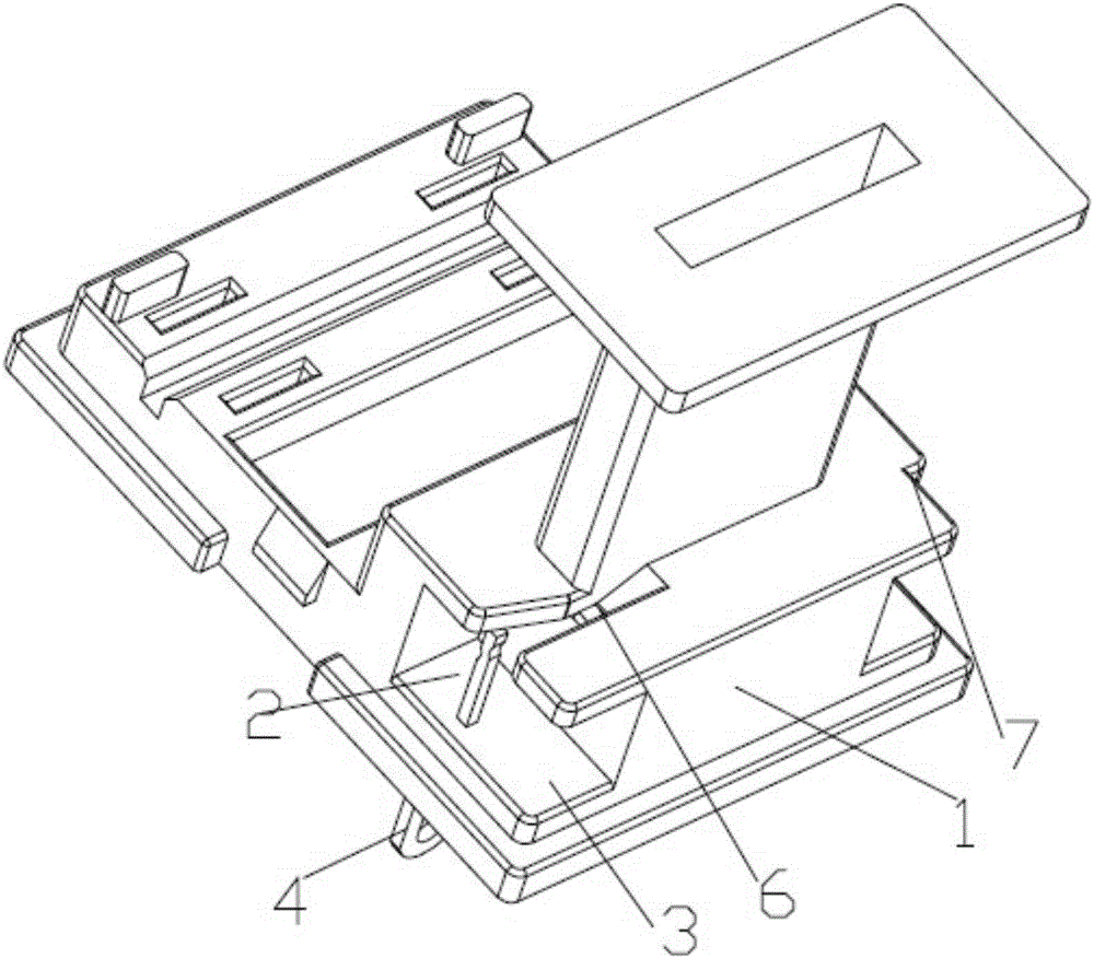
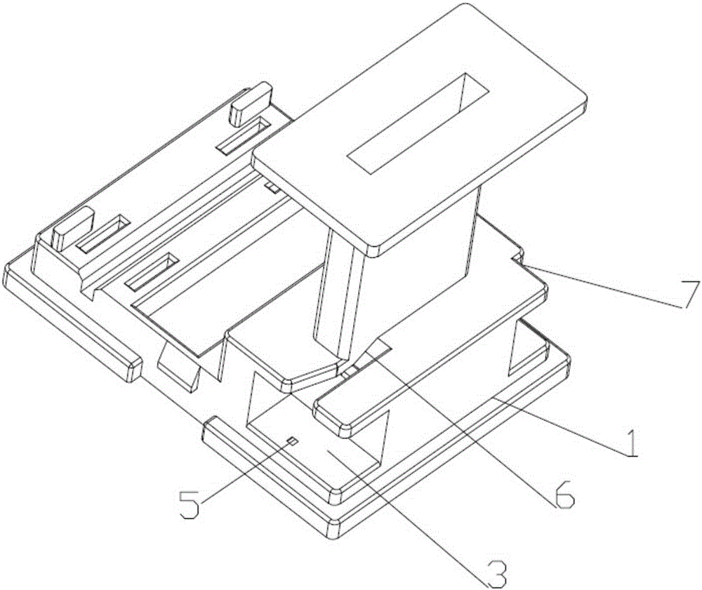
[0038] A relay with a winding device, the relay also includes a housing 14, a contact system 15, a push card 16 and a magnetic circuit assembly 17, the contact system 15 is arranged on the push card 16, the push card 16 and the magnetic circuit The assembly 17 is arranged on the installation base 1, the magnetic circuit assembly 17 drives the contact system 15 to operate as a moving contact by pushing the card 16, the cover of the housing 14 is connected to the installation base 1, and the magnetic circuit assembly 17 It includes a U-shaped iron core 18, an armature 19 and a yoke 20. The yoke 20 and the U-shaped iron core 18 are die-cast integrally. One end of the U-shaped iron core is inserted from the bottom surface of the installation base 1. One end of the armature 19 is connected to the U-shaped The U-shaped iron core 18 is connected, and the other end of the armature 19 and the end of the yoke 20 on the U-shaped iron core 18 form a magnetic pole surface.

[0039]In Embod...


PUM


Abstract

The present invention discloses a wire winding device of a relay. The wire winding device of the relay comprises a mounting base; the mounting base is provided with a wire winding assembly; the wire winding assembly comprises a wire winding groove and a coil lead-out sheet; and the coil lead-out sheet is arranged in the wire winding groove. According to the wire winding device of the relay, the rear end of the mounting base is provided with the wire winding groove; a coil lead-out sheet positioning hole is formed at the bottom of the wire winding groove; one end of the coil lead-out sheet passes through the coil lead-out sheet positioning hole and enters the wire winding groove; an enameled wire sleeves and is wound on a coil frame; two ends of the coil are connected with the coil lead-out sheet in the wire winding groove through an initial groove and an end groove respectively; and therefore, wire wound ends will not be exposed and damaged.

Description

technical field [0001] The invention relates to a relay component, in particular to a relay winding device. Background technique [0002] In the production of traditional relays, the coil frame is an indispensable part of the electromagnetic relay. The winding assembly is formed after the coil frame is wound with enameled wire and the corresponding plug-in chip is assembled. The original coil frame structure starts from a section when winding. When it is exposed on the end face of the coil frame, the thread needle constantly collides with the end face and the starting line every time the wire is routed, there is a certain risk of damaging the paint layer, and due to the accumulation of tolerances, the flatness of the winding coil surface is reduced. In addition, it is used for enameled wire Pulling from the upper end of the bobbin to the insert chip, it will be damaged by the impact force during plastic injection molding during overmolding. Contents of the invention [00...

Claims


Application Information

Patent Timeline
Patent Type & Authority Applications(China)
IPC IPC(8): H01H50/44H01H49/00
CPCH01H50/44H01H49/00H01H50/443H01H2050/446
Inventor 里奥颇得·马特周干善吴灵勇卓彬
Owner 宁波金海电子有限公司
Why Eureka
Try Eureka