Method and device for controlling a booster circuit

A booster circuit and inductance technology, applied in the circuit field, can solve the problems affecting the life of the converter and the service life of the flying capacitor, so as to improve the service life, reduce the effective value of the current, and improve the life of the whole machine Effect

Active Publication Date: 2019-04-19
HUAWEI DIGITAL POWER TECH CO LTD
View PDF3 Cites 0 Cited by
  • Summary
  • Abstract
  • Description
  • Claims
  • Application Information

AI Technical Summary

Problems solved by technology

The heating of the flying capacitor will affect the service life of the flying capacitor, and then affect the life of the boost circuit and the converter where the boost circuit is located

Method used


Image

  • Method and device for controlling a booster circuit
  • Method and device for controlling a booster circuit
  • Method and device for controlling a booster circuit

Examples


Embodiment Construction

[0033] In order to better understand the above objects, schemes and advantages of the embodiments of the present invention, a detailed description is provided below. The detailed description sets forth various embodiments of apparatuses and / or methods by using block diagrams, flowcharts, etc. figures and / or examples. In such block diagrams, flowcharts and / or examples, one or more functions and / or operations are included. Those skilled in the art will understand that: the various functions and / or operations in these block diagrams, flowcharts or examples can be implemented individually or jointly by various hardware, software, and firmware, or by any combination of hardware, software, and firmware. Composite implementation.

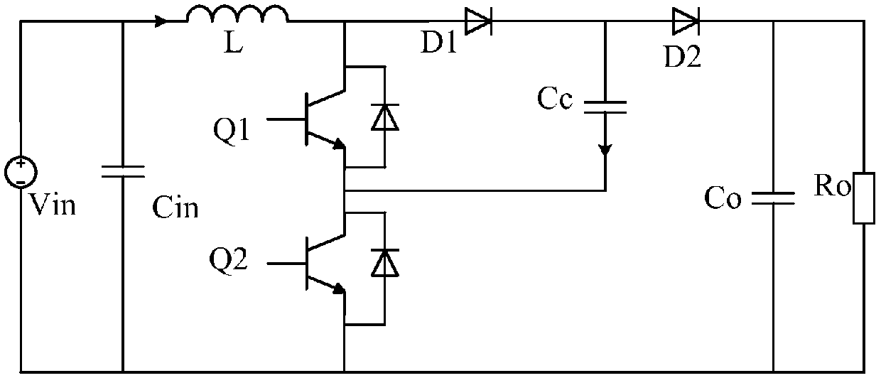
[0034]The embodiment of the present invention relates to controlling the boost circuit by driving a switch tube in the boost circuit. The inductance in the boost circuit can be charged or discharged by controlling the switching tube in the boost circuit ...


PUM


Abstract

A control method of a boosted circuit and an apparatus thereof are disclosed. The method and the apparatus are used to reduce an effective current value of a flying capacitor in the boosted circuit and decrease a heating degree of the flying capacitor so as to prolong a service life of the flying capacitor. The method comprises the following steps of configuring a first driving signal of one switch tube in the boosted circuit and a second driving signal of another switch tube, wherein a signal period of the first driving signal is less than a signal period of the second driving signal, and a duty ratio of the first driving signal is the same with a duty ratio of the second driving signal; and through the configured first driving signal and the second driving signal, controlling the boosted circuit.

Description

technical field [0001] The invention relates to the field of circuit technology, in particular to a control method and device for a booster circuit. Background technique [0002] The boost (BOOST) circuit can boost the input DC voltage and output a higher DC voltage. Due to its convenient driving and simple control, boost circuits are widely used in converters such as power factor correctors and photovoltaic inverters. [0003] figure 1 The boost circuit shown is a common flying capacitor clamping boost circuit, in which the flying capacitor is used to clamp the potential of the switch tube in the boost circuit. exist figure 1 In the boost circuit shown, Vin is the input voltage, the voltage across the resistor Ro is the output voltage, Cc is the flying capacitor, Cin and Co are the filter capacitors, L is the inductor, Q1 and Q2 are the switch tubes, D1 and D2 are diode. [0004] controlled by driving Q1 and Q2 figure 1 When the boost circuit shown is used to boost th...

Claims


Application Information

Patent Timeline
Patent Type & Authority Patents(China)
IPC IPC(8): H02M3/158
CPCH02M3/158
Inventor 石磊王朝辉傅电波
Owner HUAWEI DIGITAL POWER TECH CO LTD
Why Eureka
Try Eureka