
Method and device for increasing switching distance

A technology of distance and target base station, which is applied in the field of increasing handover distance and can solve the problems of increasing handover distance, small distance, and inability to meet user needs.

Inactive Publication Date: 2019-12-17
BEIJING XINWEI TELECOM TECH
View PDF5 Cites 0 Cited by
  • Summary
  • Abstract
  • Description
  • Claims
  • Application Information

AI Technical Summary

Problems solved by technology

[0005] In view of this, the embodiments of the present invention provide a method and device for increasing the handover distance, so as to solve the problem in the prior art that the distance between the target base station and the current base station is too small to meet the needs of users

Method used


Image

  • Method and device for increasing switching distance
  • Method and device for increasing switching distance
  • Method and device for increasing switching distance

Examples


Embodiment 1

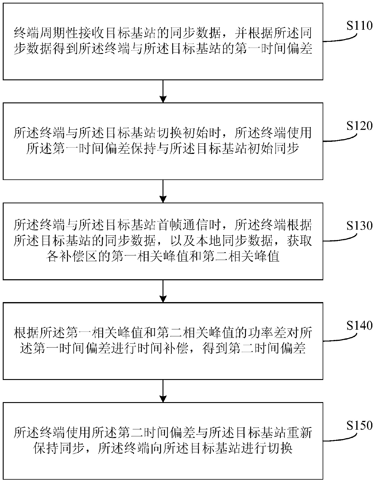
[0053] figure 1 It is a schematic flowchart of a method for increasing the switching distance provided by Embodiment 1 of the present invention. The method can be executed by a device for increasing the switching distance, wherein the device can be implemented by software and / or hardware.

[0054] Such as figure 1 As shown, the method includes:

[0055] S110. The terminal periodically receives synchronization data of the target base station, and obtains a first time offset between the terminal and the target base station according to the synchronization data;

[0056] Exemplarily, the terminal periodically receives the synchronization data sent by the target base station, and the period may be 10 ms or other time periods, which is not limited here. The terminal receives the synchronization data of the target base station according to the preset time period, performs the conversion operation from the time domain to the frequency domain on the received synchronization data, an...

Embodiment 2

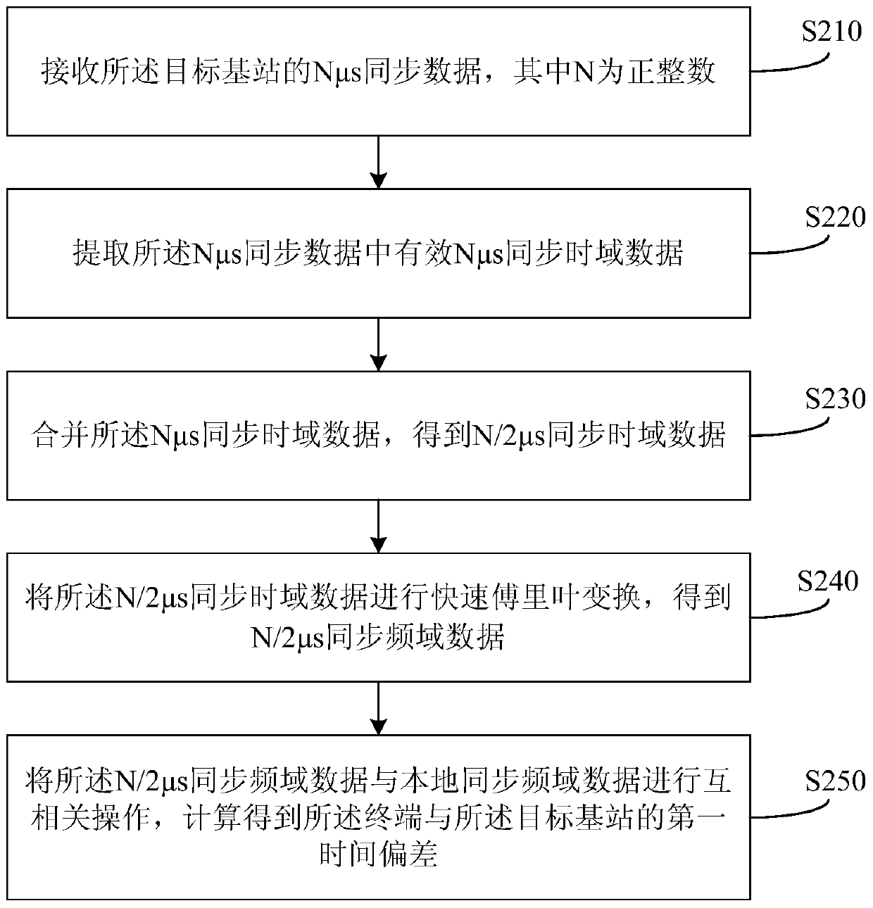
[0067] This embodiment is based on the first embodiment above, and is optimized on the basis of the first embodiment, specifically optimizing the process of obtaining the first time offset. figure 2 is a schematic flowchart of a method for increasing the switching distance provided by Embodiment 2 of the present invention, as shown in figure 2 As shown, the method includes:

[0068] S210. Receive Nμs synchronization data of the target base station, where N is a positive integer;

[0069] Exemplarily, the value of N may be 64, or 128, or 256. The synchronous data in this embodiment can be 128 μs synchronous data, namely N is 128, image 3 It is a schematic diagram of the time slot structure of synchronous data in a method for increasing the switching distance provided by Embodiment 2 of the present invention, as shown in image 3 As shown, the synchronous data time slot structure includes four parts: 310-340, wherein, 310 is a 24 μs prefix, 320 is a 64 μs synchronous data ...

Embodiment 3

[0081] This embodiment is based on the foregoing embodiments, and optimization is performed on the basis of the foregoing embodiments, specifically, the process of obtaining the second time offset, that is, the process of time compensation, is optimized. Figure 5 is a schematic flowchart of a method for increasing the switching distance provided by Embodiment 3 of the present invention, as shown in Figure 5 As shown, the method includes:

[0082] S510. Receive Nμs synchronization data of the target base station;

[0083] Exemplarily, the value of N may be 64, or 128, or 256. The synchronous data in this embodiment may be 128 μs synchronous data, that is, N is 128. Receive target base station 128μs synchronization data.

[0084] S520. Extract effective Nμs synchronization time domain data from the Nμs synchronization data;

[0085] Exemplarily, effective 128 μs synchronous time domain data Tsync_128 in the 128 μs synchronous data is extracted.

[0086] S530. Perform fast...


PUM


Abstract

The invention discloses a method and device for lengthening the switching distance. The method includes the steps that a terminal periodically receives synchronous data of a target base station, and a first time deviation of the terminal and the target base station is obtained according to the synchronous data; when the terminal and the target base station are subjected to initial switching, the terminal and the target base station keep initial synchronization through the first time deviation; when the terminal is in communication with the target base station in first frame, the terminal obtains first correlation peak values and second correlation peak values of all compensation areas according to the synchronous data of the target base station and local synchronous data; the first time deviation is subjected to time compensation according to the power differences of the first correlation peak values and the second correlation peak values, and a second time deviation is obtained; the terminal and the target base station keep synchronization newly through the second time deviation, and the terminal is switched to the target base station. By means of the method and device for lengthening the switching distance, the problem that in the prior art, as the distance between a target base station and a current base station is small, the requirements of a user cannot be met is solved.

Description

technical field [0001] The invention relates to the technical field of mobile communication, in particular to a method and a device for increasing the switching distance. Background technique [0002] Handover in mobile communication refers to the process that the mobile station needs to transfer from the original channel to a more suitable channel for information transmission due to various reasons when transmitting information between the mobile station and the base station. At present, the Multi-Carrier Wireless Information Local Loop (McWill) system adopts two handover methods, one is every frame handover, and the terminal communicates with the current base station and the target base station alternately during the handover process. One way is to ensure that the service of the terminal is not interrupted during the handover process; another handover way is forced handover. When the quality of the communication link is not good, the base station controller notifies the te...

Claims


Application Information

Patent Timeline
Patent Type & Authority Patents(China)
IPC IPC(8): H04W36/00H04W36/08
CPCH04W36/0072H04W36/08
Inventor 韩红娟赵渊王联埕
Owner BEIJING XINWEI TELECOM TECH
Learn More