A capillary driven flat plate evaporator fluid circuit

A fluid circuit and evaporator technology, which is applied in the field of cryogenic heat transfer devices to solve the problems of miniaturization and supercritical start-up, is conducive to miniaturization design, and reduces the quality of liquid work.

Inactive Publication Date: 2013-10-23
BEIJING INST OF SPACECRAFT SYST ENG
View PDF0 Cites 3 Cited by
  • Summary
  • Abstract
  • Description
  • Claims
  • Application Information

AI Technical Summary

Problems solved by technology

Through retrieval, do not see the related report of the miniaturization design of domestic and foreign relevant cryogenic heat transfer device

Method used


Image

  • A capillary driven flat plate evaporator fluid circuit
  • A capillary driven flat plate evaporator fluid circuit

Examples


Embodiment Construction

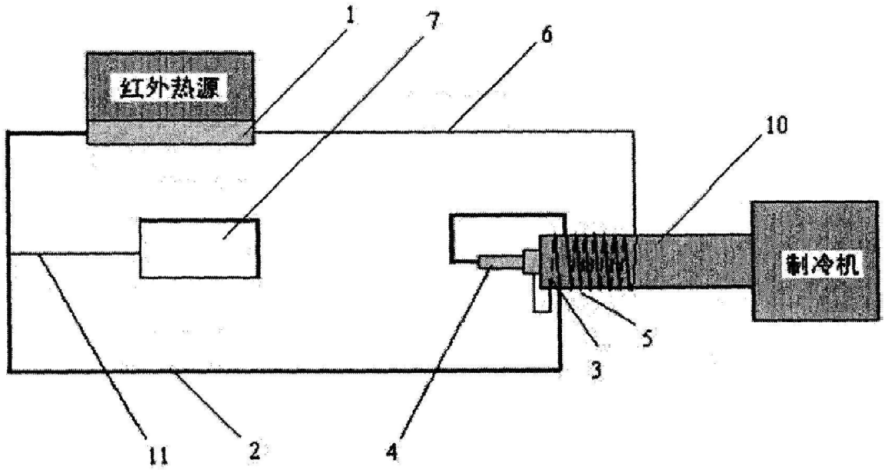
[0018] The present invention provides capillary force-driven plate evaporator fluid circuit, as shown in Figure 1.

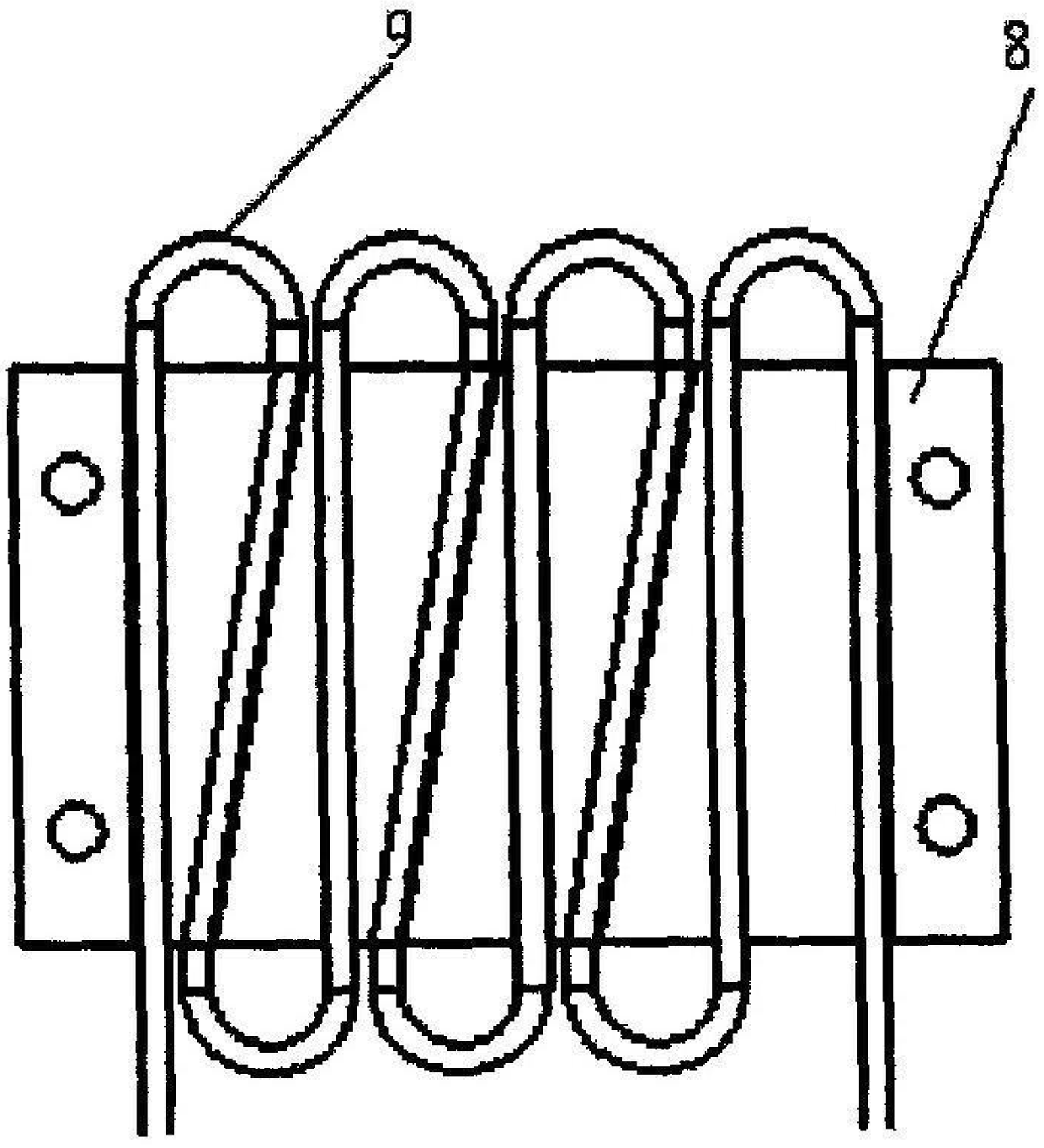
[0020] The auxiliary condensation pipe 3 and the main condensation pipe 5 are brazed in the groove of the condensation column 10 to increase the heat transfer effect. steam line 2

[0023] The plate evaporator 1 is thermally coupled with an infrared heat source, and the condensation column 10 is coupled with a refrigerator. Capillary evaporator 4 with condensation

[0024] The capillary evaporator in this embodiment can also be connected to a liquid reservoir.

[0026] The plate evaporator 1 is coupled with an infrared heat source, which can collect heat from the heat source. Condensation column 10 is coupled with refrigerator, can


PUM


Abstract

The invention discloses a fluid circuit of a capillary force-driven flat plate evaporator, which comprises a flat plate evaporator (1), a steam pipeline (2), an auxiliary condensation pipe (3), a capillary evaporator (4), a main The condensing pipe (5) and the liquid pipeline (6), the auxiliary condensing pipe (3) and the main condensing pipe (5) are wound on the condensing column (10), and the steam pipeline (2) is connected to the gas storage chamber (7); The flat plate evaporator (1) includes a heat conduction plate (8) and a serpentine pipe (9) embedded in the upper channel of the heat conduction plate (8); the plate evaporator (1) is coupled with an infrared heat source, and the condensation column (10) is coupled with a refrigerator ; The capillary evaporator (4) is in direct contact with the condensation column (10). The invention adopts the form of a flat plate evaporator and only includes one capillary evaporator, and realizes the miniaturization of the structure while solving the supercritical start-up of the cryogenic heat transfer device.

Description

A capillary force-driven flat plate evaporator fluid circuit technical field The present invention relates to the cryogenic heat transfer device of space application background, particularly a kind of evaporator driven by capillary force fluid circuit. Background technique In the face of space-based infrared satellites etc. to the special demand of space cold source, must be in infrared detector and space deep low temperature refrigeration Create a "bridge" between the cold machines, that is, the cryogenic heat transfer device. In addition to the need to achieve cryogenic conditions, the cryogenic heat transfer device The high-efficiency collection and transmission of heat will also have the function of isolating or reducing mechanical vibration and electromagnetic interference. for space applications Background, at present, the cryogenic heat transfer device mainly needs to solve two technical problems: 1) solve the supercritical start-up from the normal temperature...

Claims


Application Information

Patent Timeline
Patent Type & Authority Patents(China)
IPC IPC(8): F28D15/02H05K7/20
Inventor 莫青张红星丁汀苗建印
Owner BEIJING INST OF SPACECRAFT SYST ENG
Why Eureka
Try Eureka