
A steel strip bending device

A bending device and a technology for steel strips, which are used in manufacturing tools, metal processing, perforating tools, etc., can solve problems such as unfavorable promotion and high performance requirements of mechanical arms, and achieve a simple and compact structure, easy to promote, and reduce clamping force. desired effect

Active Publication Date: 2018-08-24
INST OF INTELLIGENT MFG GUANGDONG ACAD OF SCI
View PDF6 Cites 0 Cited by
  • Summary
  • Abstract
  • Description
  • Claims
  • Application Information

AI Technical Summary

Problems solved by technology

However, this method has high requirements on the performance of the mechanical arm, which is not conducive to the promotion in actual production.

Method used


Image

  • A steel strip bending device
  • A steel strip bending device
  • A steel strip bending device

Examples


Embodiment Construction

[0047] The present invention will be further described in detail below in conjunction with the embodiments and the accompanying drawings, but the embodiments of the present invention are not limited thereto.

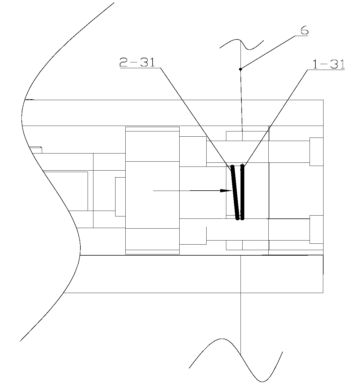
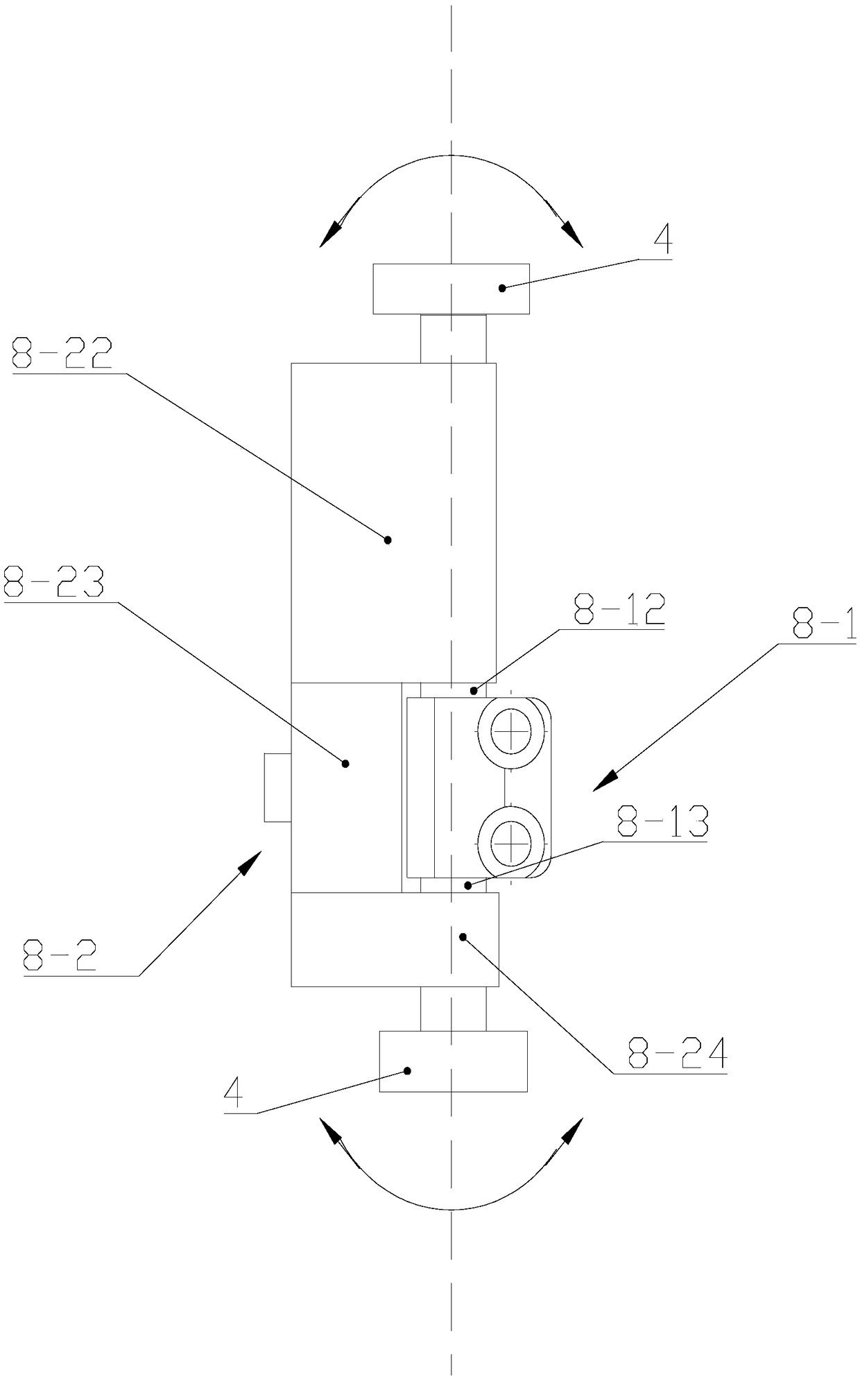
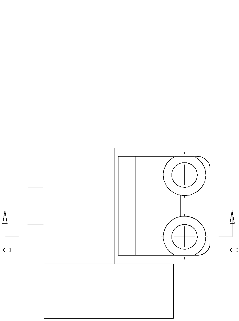
[0048] see Figure 1 to Figure 5 , a steel strip bending device 8 of the present invention includes a bending fixed seat 8-1 fixedly connected to the frame 4, a bending rotating seat 8-2 connected to the frame 4 through a rotating structure, and a driving bending seat 8-1. The second drive mechanism 8-3 for the movement of the rotating base 8-2; wherein, the bending rotating base 8-2 is composed of an upper connecting block 8-22, a middle bending block 8-23 and a lower connecting block 8 -24, the upper end and the lower end of the bending fixing seat 8-1 are respectively provided with an upper rotating shaft 8-12 and a lower rotating shaft 8-13, and the upper rotating shaft 8-12 extends from the bottom surface of the upper connecting block 8-22 The upper connecting bloc...


PUM


Abstract

The invention discloses a steel strip bending device. The steel strip bending device comprises a bending fixed base fixedly connected with a frame, a bending rotating base connected to the frame through a rotating structure, and a second driving mechanism for driving the bending rotating base to move; the bending rotating base consists of an upper connecting block, a middle bending block and a lower connecting block connected together; an upper rotating shaft and a lower rotating shaft are respectively arranged at the upper end and the lower end of the bending fixed base; the upper rotating shaft extends into the upper connecting block to form rotary connection; the lower rotating shaft extends into the lower connecting block to form rotary connection; a fixed bending surface is arranged on the bending fixed base; a rotating bending surface is arranged on the bending rotating base; the fixed bending surface and the rotating bending surface are arranged in a manner of face to face; and a second steel strip conveying channel is formed between the fixed bending surface and the rotating bending surface. The steel strip bending device can bend end parts of steel strips, is convenient for clamping by a manipulator through the bent parts, and is convenient to pull the steel strips.

Description

technical field [0001] The invention relates to material bending equipment, in particular to a steel strip bending device. Background technique [0002] In the production process of the transformer, it is necessary to use a thin steel strip to spirally wind the three-dimensional wound core of the transformer. In actual production, the steel strip needs to be pulled out from the steel coil to a certain length and cut off, and then wound with the cut steel strip. In the operation of pulling the steel belt, since the friction force of the flat steel belt is small, it is easy to slip, so the pulling operation is difficult. In actual production, in order to solve the above problems, the method of increasing the clamping force of the mechanical arm is usually used to increase the pulling force to realize the pulling task of the steel strip. However, this method has high requirements on the performance of the mechanical arm, which is not conducive to the promotion in actual produ...

Claims


Application Information

Patent Timeline
Patent Type & Authority Patents(China)
IPC IPC(8): B21D5/00B21C51/00B21D28/26B21D28/34B21D28/02B21D28/14B21D35/00
CPCB21C51/00B21D5/00B21D28/02B21D28/14B21D28/26B21D28/34B21D35/001B21D35/002
Inventor 陈启愉段先云吴智恒李平
Owner INST OF INTELLIGENT MFG GUANGDONG ACAD OF SCI
Features
  • Generate Ideas
  • Intellectual Property
  • Life Sciences
  • Materials
  • Tech Scout
  • Unparalleled Data Quality
  • Higher Quality Content
  • 60% Fewer Hallucinations
Learn More