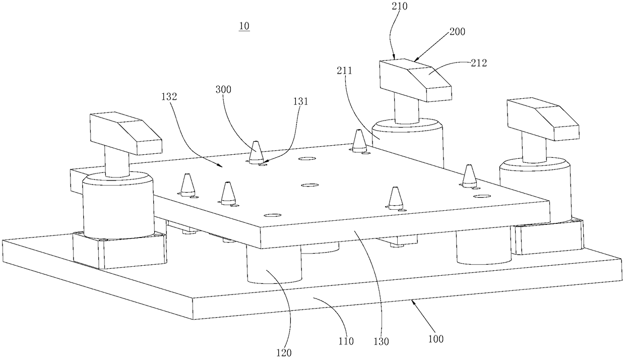
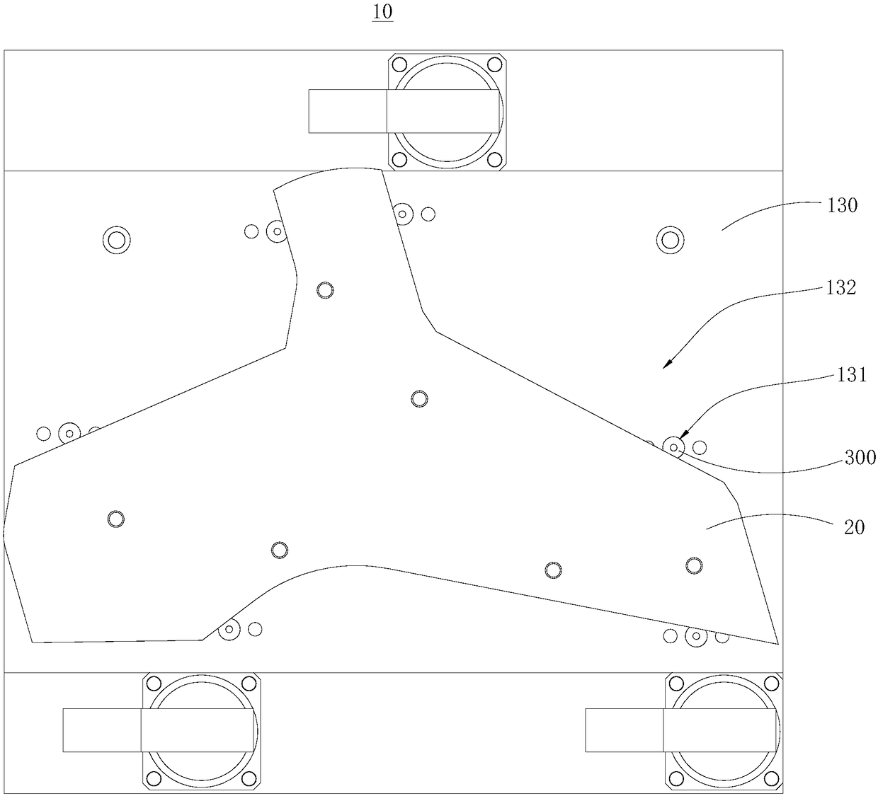
sheet metal positioning mechanism

A positioning mechanism and metal plate technology, applied in the field of hardware parts processing, can solve the problems of poor universality, increased production cost, narrow applicability of fixing grooves, etc., and achieve high universality, high positioning effect, and simple and convenient positioning operation. Effect

Active Publication Date: 2018-08-31
新辉精密五金(惠州)有限公司
View PDF6 Cites 0 Cited by
  • Summary
  • Abstract
  • Description
  • Claims
  • Application Information

AI Technical Summary

Problems solved by technology

[0003] The existing positioning method for the metal sheet is to set a fixing groove matching the technical sheet on the machine, and insert the metal sheet into the fixing groove. However, the processing operation of the fixing groove is complicated and cumbersome, and the application of the fixing groove Narrow compatibility, that is, poor universality, once the shape and specification of the processed metal sheet change, a new fixing groove must be designed, which increases the production cost

Method used


Image

  • sheet metal positioning mechanism
  • sheet metal positioning mechanism
  • sheet metal positioning mechanism

Examples


Embodiment Construction

[0025] In order to facilitate the understanding of the present invention, the present invention will be described more fully below with reference to the associated drawings. Preferred embodiments of the invention are shown in the accompanying drawings. However, the present invention can be embodied in many different forms and is not limited to the embodiments described herein. On the contrary, the purpose of providing these embodiments is to make the disclosure of the present invention more thorough and comprehensive.

[0026] It should be noted that when an element is referred to as being “fixed” to another element, it can be directly on the other element or there can also be an intervening element. When an element is referred to as being "connected to" another element, it can be directly connected to the other element or intervening elements may also be present. The terms "vertical," "horizontal," "left," "right," and similar expressions are used herein for purposes of ill...


PUM


Abstract

A metal board positioning mechanism comprises a base, a slide rail device and a limiting device, wherein the base comprises a bottom plate, a plurality of supporting columns and a positioning plate; a plurality of inserting holes are formed in the positioning plate; the slide rail device comprises a plurality of slide rails which are arranged on the positioning plate; each slide rail is provided with a sliding chute; the limiting device comprises a plurality of limiting assemblies, and each limiting assembly comprises a plurality of limiting parts; each limiting part comprises a limiting column, a limiting box, a limiting spring and a transverse rod; the limiting boxes are arranged in the sliding chutes in a sliding manner; the first end of each limiting column passes through the corresponding inserting hole, and the second end of each limiting column passes through the corresponding limiting box by sliding; sleeves of the limiting springs are arranged at the outsides of the limiting columns; the limiting springs are stored in the limiting boxes; the first ends of the limiting springs are connected with the transverse rods. With the adoption of the metal board positioning mechanism, a metal board can be positioned; the metal board positioning mechanism is high in universality for the metal boards with different shapes; in addition, the positioning operation is simple and convenient; and the positioning effect is high.

Description

technical field [0001] The invention relates to the technical field of hardware parts processing, in particular to a metal plate positioning mechanism. Background technique [0002] At present, in the process of manufacturing aviation equipment parts, such as civil aircraft parts, it is often necessary to drill a number of process holes on irregularly shaped metal plates to complete the drilling process. Moreover, in the drilling process, the metal sheet needs to be positioned on the machine in advance, and then the drilling equipment is used to turn the hole. In this process, the positioning operation of the metal sheet is particularly important, which directly affects the process hole. Accuracy and quality, that is, in the drilling process, avoiding the displacement of the metal sheet relative to the machine can improve the accuracy and quality of the process hole. [0003] The existing positioning method for the metal sheet is to set a fixing groove matching the technica...

Claims


Application Information

Patent Timeline
Patent Type & Authority Patents(China)
IPC IPC(8): B23Q3/08
CPCB23Q3/082
Inventor 徐鹏飞
Owner 新辉精密五金(惠州)有限公司
Why Eureka
Try Eureka