Bi-directional mechanical relieving labor-saving mechanism for parking brake of railway vehicles

A technology for parking brakes and rail vehicles, which is applied in the field of rail vehicle parking brake relief. It can solve problems such as inconvenient operating positions, potential safety hazards, and large parking brake relief force, and achieves reduced mechanical release tension, good reliability, and The effect of simple structure

Active Publication Date: 2017-05-24
CRRC CHANGCHUN RAILWAY VEHICLES CO LTD
View PDF9 Cites 1 Cited by
  • Summary
  • Abstract
  • Description
  • Claims
  • Application Information

AI Technical Summary

Problems solved by technology

[0003] What the present invention aims to solve is that the parking brake relief force is too large, the operating position is inconvenient, and there are potential safety hazards

Method used


Image

  • Bi-directional mechanical relieving labor-saving mechanism for parking brake of railway vehicles
  • Bi-directional mechanical relieving labor-saving mechanism for parking brake of railway vehicles
  • Bi-directional mechanical relieving labor-saving mechanism for parking brake of railway vehicles

Examples


Embodiment Construction

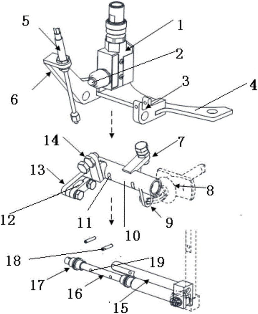
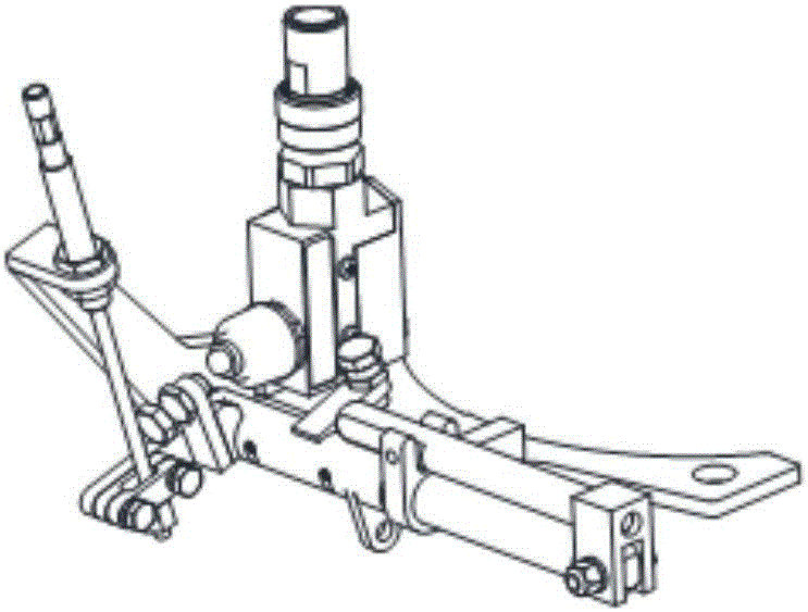
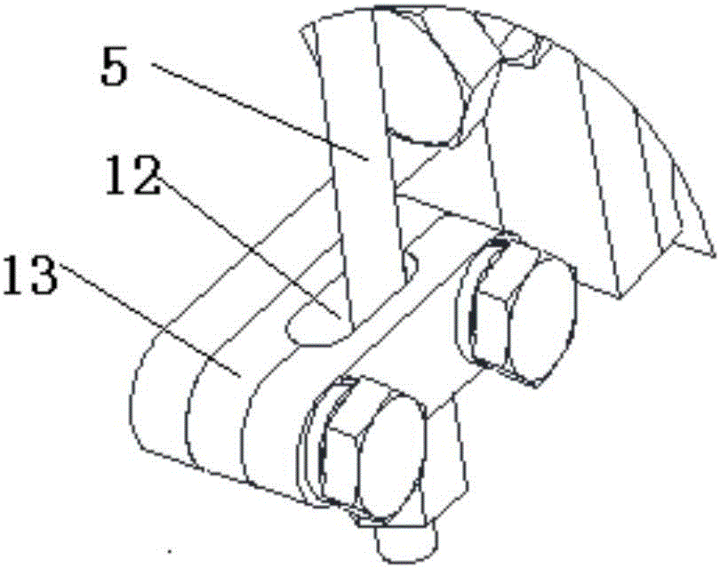
[0011] refer to figure 1 , figure 2 , the specific embodiment of the present invention comprises mounting plate 4, sleeve 10, rotating shaft 16, large and small force arms 13,9, adjustable limit stopper 7, transmission pin 18, operating handle 15 and travel switch 1 under the vehicle, and the mounting plate is used To fix the entire relief mechanism on the brake cylinder, the support plate 6 and the handle fixing clip 3 are all fixed on the mounting plate 4, and the travel switch is mounted on the mounting plate by screws. The sleeve 10 is installed on the shaft sleeve 17 of the rotating shaft 16, and is used to transmit the action of the push-pull cable 5. The sleeve 10 is provided with four oblong holes 11 in two pairs, the large and small moment arms 13, 9, and the travel switch trigger point 14 , Adjustable limit stops 7 are all fixed together with the sleeve 10. The big arm 13 is used to connect the push-pull steel cable, and the small moment arm is used to connect the...


PUM


Abstract

The invention provides a bi-directional mechanical relieving labor-saving mechanism for parking brake of railway vehicles. One end of a mounting plate is connected with a supporting plate and a travel switch, and a handle fixation clamp is arranged in the middle of the mounting plate. One end of a rotating shaft penetrates through the handle fixation clamp and is rotatably matched with the handle fixation clamp, and the other end of the rotating shaft is installed on the supporting plate. A sleeve is arranged on the rotating shaft, two long circular holes are formed in the surface of the sleeve, and two through circular holes are formed in the rotating shaft. Transmission pins are inserted into the circular holes in the rotating shaft and then penetrate through the long circular holes of the sleeve. A large force arm is fixedly connected with one end of the sleeve, and a small force arm is fixedly connected with the other end of the sleeve. A trigger point of the travel switch is installed on the sleeve and corresponds to a contact of the travel switch. The upper half portion of a push-pull steel cable is clamped on the supporting plate through two back nuts, and the lower portion of the push-pull steel cable penetrates through a long circular hole in the large force arm. The mounting plate is used for mounting the whole relieving mechanism and a brake cylinder. According to a relieving structure, both relieving operation on the vehicles and relieving operation under the vehicles can be triggered, and a parking brake mechanical relieving state can be conveniently checked; meanwhile, mechanical relieving tensile force for parking brake is greatly lowered, the operation time is greatly shortened for drivers and maintainers, and labor intensity of the drivers and the maintainers is greatly relieved; and the bi-directional mechanical relieving labor-saving mechanism for parking brake of the railway vehicles is simple in structure, convenient to use and good in reliability.

Description

technical field [0001] The invention belongs to the technical field of rail vehicle parking brake relief, and in particular relates to a parking brake bidirectional mechanical relief and labor-saving mechanism. Background technique [0002] In order to ensure the parking braking force requirements of rail vehicles on ramps or garages, the foundation braking device of rail vehicles is usually equipped with a parking brake device, which is usually applied by spring force and released by air. In order to ensure that the rail vehicle can release the parking brake without compressed air, the foundation brake device is usually equipped with a manual release device to relieve the spring parking brake force generated by the parking brake device. The manual release ring of the parking brake device is located near the wheel. When the parking brake force needs to be released, the release ring of the parking brake cylinder is connected through an ordinary steel wire rope. The end of the...

Claims


Application Information

Patent Timeline
Patent Type & Authority Applications(China)
IPC IPC(8): B61H13/02
CPCB61H13/02
Inventor 张彦平杨洋刘洪涛石雪娇丁富昌
Owner CRRC CHANGCHUN RAILWAY VEHICLES CO LTD
Why Eureka
Try Eureka