Waste gas incineration device

An incineration device and exhaust gas technology, which is applied in the direction of incinerators, combustion types, combustion methods, etc., can solve the problems of large temperature fluctuations in the catalytic bed, unsuitable treatment of concentrated organic waste gas, large internal airflow resistance and switching of wind direction, etc., to achieve good heat capacity and thermal conductivity, easy installation, and less flow channel wind resistance

Active Publication Date: 2018-10-23
FOSHAN ANJIEBAO ENERGY SAVING EQUIP CO LTD
View PDF10 Cites 0 Cited by
  • Summary
  • Abstract
  • Description
  • Claims
  • Application Information

AI Technical Summary

Problems solved by technology

Although catalytic incineration (CO) does not need to switch the wind direction, because there is not enough regenerator inside the furnace, when the concentration of exhaust gas varies greatly, the heat generated by pyrolysis changes rapidly, which easily causes the temperature of the catalytic bed to fluctuate greatly and be damaged. Catalytic incinerator is not suitable for treating organic waste gas with high concentration
Although regenerative catalytic incineration (RCO) has regenerative ceramic blocks to stabilize the internal temperature, it also has the same defects as RTO due to the large internal airflow resistance and the need to switch the wind direction

Method used


Image

  • Waste gas incineration device
  • Waste gas incineration device
  • Waste gas incineration device

Examples


Embodiment 1

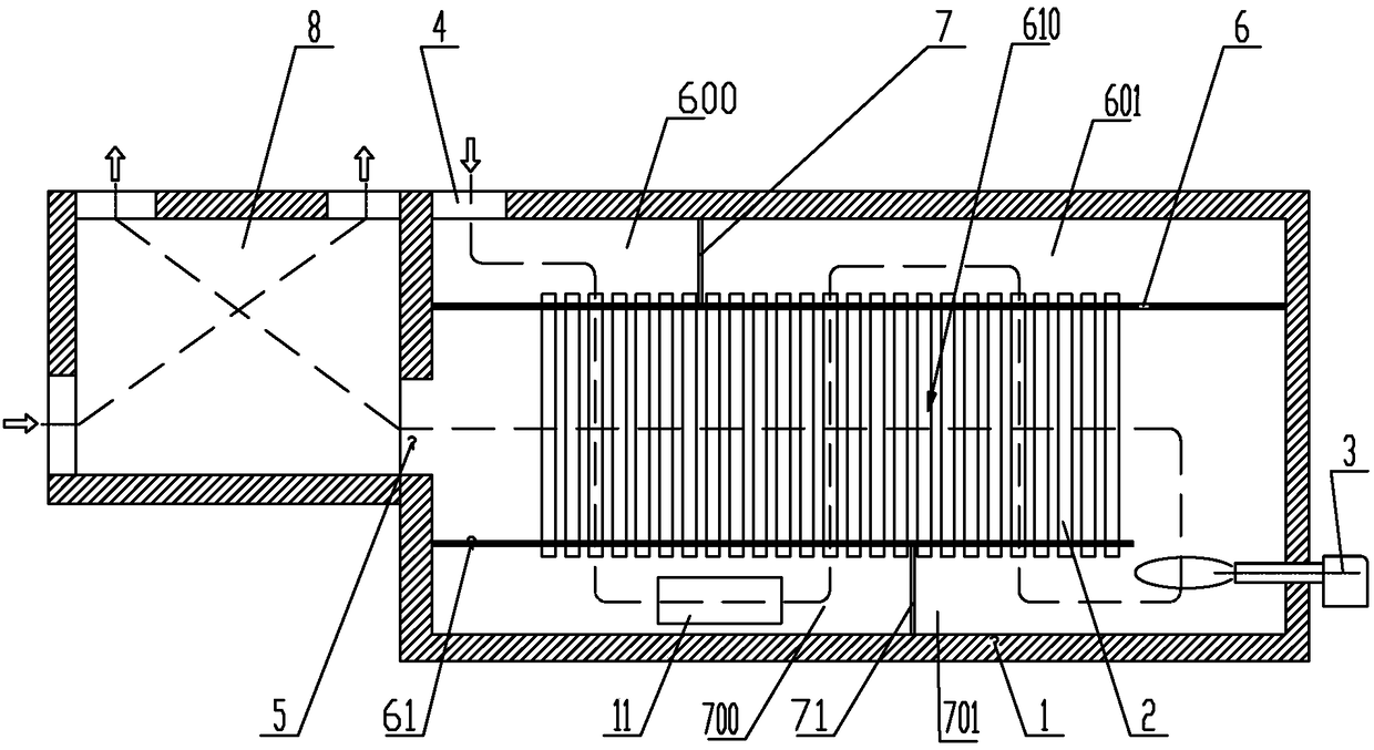
[0039] Embodiment 1: as figure 1 As shown, a waste gas incineration device is composed of a furnace 1, a heat storage tube 2, a heater 3, an air inlet 4, an air outlet 5 and a flue gas cooler 8. The upper part of the furnace 1 is provided with an upper sealing end plate 6. The upper sealing end plate 6 and the inner wall of the furnace enclose a sealed space, and a first partition 7 is arranged in the space, and the first partition 7 divides the space into a first upper air passage space 600 (equivalent to the first M upper wind passage spaces, where M=1), the second upper wind passage space 601 (equivalent to the M+1th upper wind passage space, where M=1).

[0040] The lower part of the furnace 1 is provided with a lower sealing end plate 61, which forms a sealed space with the inner wall of the furnace, and a second partition is arranged in the space, and the second partition 71 divides the space into The first lower wind passage space 700 (equivalent to the Lth lower wind ...

Embodiment 2

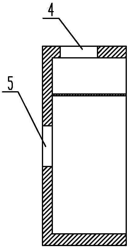
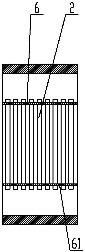
[0063] Embodiment 2: as figure 2 , image 3 , Figure 4 , Figure 5 : a modular waste gas incinerator, the overall structure is the same as the embodiment. The furnace and the components located in the furnace constitute the main body of the furnace; the main body of the furnace is divided into three modules, including the air inlet and outlet modules (such as figure 2 ), thermal storage modules (such as image 3 ) and heating modules (such as Figure 4 ), the air outlet module, heat storage module and heating module are combined to form the entire furnace body. The air inlet and outlet module is provided with an air inlet 4 and an air outlet 5, and the structure is a square cavity with one side opening; the heat storage module is a square frame with two sides opening, and a plurality of vertical heat storage tubes 2 are arranged inside; The structure of the heating module is a square cavity with an opening on one side, and a heater 3 is arranged inside it. The air inl...


PUM


Abstract

The invention discloses a waste gas incinerator which comprises a hearth, a heat accumulation pipe, a heater, an air inlet, an air outlet and a smoke cooler. An upper sealing end plate is arranged at the upper portion of the interior of the hearth. An upper portion air passing space is formed in the sealed space defined by the upper sealing end plate and the inner wall of the hearth. A lower sealing end plate is arranged at the lower portion of the interior of the hearth, and a lower portion air passing space is formed in the space defined by the lower sealing end plate and the inner wall of the hearth. Waste gas and smoke conduct heat exchange through the wall of the heat accumulation pipe so that the two kinds of gases cannot be mixed mutually, and the waste gas incinerator does not need to switch the flow directions of waste gas and smoke in turns to complete the heat exchange process of heat accumulation and heat releasing like a traditional heat accumulation incinerator. The heat accumulation pipe in the hearth has good thermal capacity and heat conductivity, fast heat absorbing and releasing can be achieved due to the good heat accumulation performance of the heat accumulation pipe, and acute fluctuation of the temperature of the hearth is reduced.

Description

technical field [0001] The invention relates to a waste gas incineration device, in particular to an incineration device for the harmless treatment of organic waste gas, belonging to the technical field of environmental protection. Background technique [0002] At present, for the harmless pyrolysis treatment of organic waste gas, regenerative incineration (RTO) and catalytic incineration (CO or RCO) are mainly used. Regenerative incineration has a wide range of applicability to the components of waste gas to be treated, but the equipment has complex structure, large size, long installation period and high cost. The heat storage incinerator adopts two or more heat storage tanks, and the storage tanks are equipped with heat storage ceramic blocks. The heat storage and heat release process is completed by switching the airflow direction of the heat storage ceramic blocks in turn to realize the waste gas and flue gas. heat exchange between them. However, in this technology, t...

Claims


Application Information

Patent Timeline
Patent Type & Authority Patents(China)
IPC IPC(8): F23G7/06
CPCF23G7/068F23G2201/101F23G2206/10F23G2209/14
Inventor 林景峰
Owner FOSHAN ANJIEBAO ENERGY SAVING EQUIP CO LTD
Why Eureka
Try Eureka