Check patentability & draft patents in minutes with Patsnap Eureka AI!

Electronic card connecting device

A technology for connection devices and electronic cards, which is applied in the direction of preventing wrong connections, connections, coupling devices, etc., and can solve problems such as the inability to set anti-reverse insertion structures

Active Publication Date: 2017-05-24
MOLEX INC
View PDF7 Cites 0 Cited by
  • Summary
  • Abstract
  • Description
  • Claims
  • Application Information

AI Technical Summary

Problems solved by technology

[0003] However, the anti-reverse insertion structure of the aforementioned prior art drawer base requires the cooperation of the crimping wall of the insulating body to achieve the anti-reverse insertion effect. When the drawer type card connector does not have the crimping wall of the insulating body, it cannot Set the above anti-reverse insertion structure

Method used


Image

  • Electronic card connecting device
  • Electronic card connecting device
  • Electronic card connecting device

Examples


Embodiment Construction

[0073] Before the present invention is described in detail, it should be noted that in the following description, similar elements are denoted by the same numerals.

[0074] The following description of the embodiments refers to the accompanying drawings to illustrate specific embodiments in which the invention may be practiced. The directional terms mentioned in the present invention, such as "upper", "lower", "front", "rear", "left", "right", etc., are only referring to the directions of the accompanying drawings. Accordingly, the directional terms are used to illustrate, not to limit, the invention.

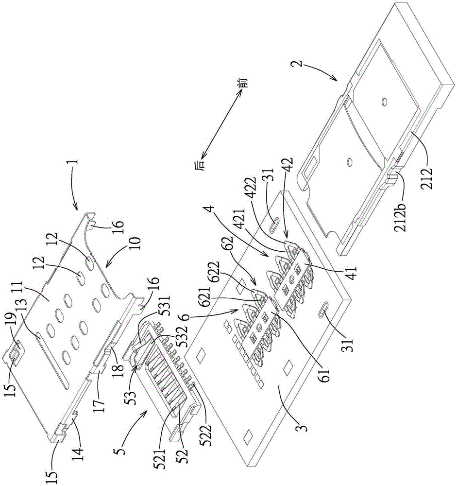
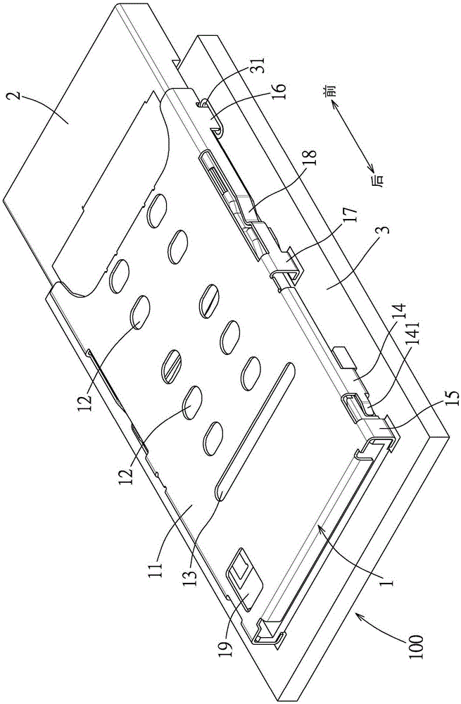
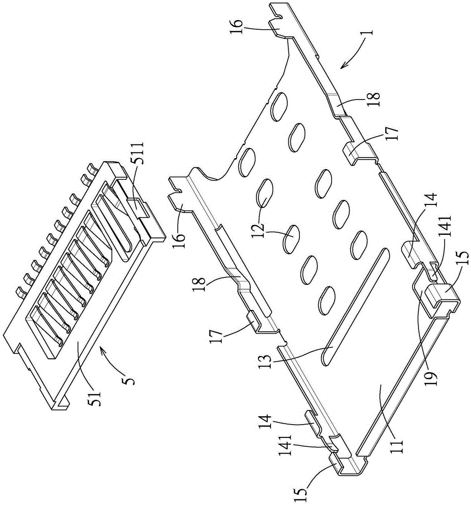
[0075] refer to figure 1 , figure 2 and image 3 , an embodiment of the electronic card connection device of the present invention includes a card connector 100 and an electronic card tray 2 .

[0076] The card connector 100 includes a metal cover 1 , a substrate 3 , a first terminal module 4 , a second terminal module 5 and a third terminal module 6 . The metal upper co...


PUM


Abstract

The invention discloses an electronic card connecting device, which comprises a card connector and an electronic card tray, wherein the card connector comprises a substrate, a first terminal module and a metal upper cover; the first terminal module is arranged on the substrate and comprises an insulating base portion, the metal upper cover is arranged on the substrate and covers the first terminal module, and the metal upper cover, the substrate and the first terminal module are mutually matched to define a card inserting space; the electronic card tray comprises a frame and a bottom plate arranged at the bottom side of the frame; the frame and the bottom plate are mutually matched to define an internal space, the frame is provided with two side frame strips with each side frame strip being provided with a locking portion, and the rear end of the bottom plate is provided with a rear-end guide portion which is bent towards the direction of the internal space. When the electronic card tray is inserted into the card inserting space with the two blocking portions facing upward, the electronic card tray is lifted to the insulating base portion by the aid of the guidance that the rear-end guide portion is contacted with the front end of the insulating base portion of the first terminal module, and then the electronic card tray is prevented from getting into the card inserting space through abutting the two blocking portions against the front edge of the metal upper cover.

Description

technical field [0001] The invention relates to a connector, in particular to an electronic card connection device. Background technique [0002] In the prior art, for example, Chinese Patent No. CN201220741454.0 (Taiwan Patent Corresponding Case M459569) discloses a drawer-type card connector, which includes an insulating body, a plurality of conductive terminals accommodated in the insulating body, and is covered on the insulating body The shielding shell and the drawer seat for carrying the electronic card. The shielding shell and the insulating body jointly form a plug-in space. The insulating body includes a flat bottom wall and crimping walls extending upward from both sides of the bottom wall; and the drawer base can be inserted into and pulled out of the plug-in space. The drawer base includes a main body and an operating portion fixed at one end of the main body, and an anti-reverse insertion structure is provided at the chamfer of the other end of the main body to...

Claims


Application Information

Patent Timeline
Patent Type & Authority Applications(China)
IPC IPC(8): H01R12/71H01R13/64
Inventor 陈智伟林健兴
Owner MOLEX INC
Features
  • R&D
  • Intellectual Property
  • Life Sciences
  • Materials
  • Tech Scout
  • Unparalleled Data Quality
  • Higher Quality Content
  • 60% Fewer Hallucinations
Learn More