Electricity supply connection plates

A connection board and group connection technology, which is applied in the direction of electromagnetic terminals/connectors, circuits, electromagnets, etc., can solve the problems of heavy workload, uneconomical, and complicated connection operations, and achieve workload reduction, efficient connection operations, and less The effect of setting the area

Active Publication Date: 2017-05-24
MITSUBISHI ELECTRIC CORP
View PDF6 Cites 0 Cited by
  • Summary
  • Abstract
  • Description
  • Claims
  • Application Information

AI Technical Summary

Problems solved by technology

[0006] When connecting electromagnets in the past, due to the above-mentioned structure, when connecting the power supply cable to the electromagnet on site, especially in the case of a large electromagnet that requires a large current, there are problems such as the following: Laying many large-diameter power cables complicates the connection work during laying, and the large-diameter power cables are difficult to handle, such as being difficult to bend. The workload is also very large, which is inefficient and uneconomical.

Method used


Image

  • Electricity supply connection plates
  • Electricity supply connection plates
  • Electricity supply connection plates

Examples


Embodiment approach 1

[0027] Next, Embodiment 1 of the present invention will be described based on the drawings.

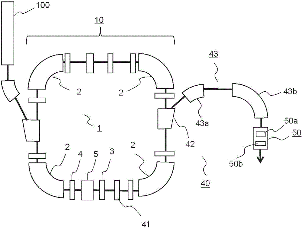
[0028] figure 1 A plan view showing a device using the synchrotron 1 which is an accelerator according to Embodiment 1 of the present invention, such as a particle beam therapy device or the like. A particle beam that is a collection of hydrogen ions (protons) or carbon ions generated by the ion source of the injector 100 is pre-accelerated to a predetermined energy by the linear accelerator of the injector 100 . The pre-accelerated particle beams are ejected from the injector, subjected to deflection, convergence and divergence, orbit correction by various electromagnets, and guided to the synchrotron 1. The synchrotron 1 is equipped with various electromagnets such as deflection electromagnet 2, orbit correction electromagnet 3, convergence or divergence electromagnet 4, etc., so that the particle beam rotates along the orbit in the synchrotron 1 as an accelerator, and repeatedly ...


PUM

PropertyMeasurementUnit
lengthaaaaaaaaaa
lengthaaaaaaaaaa

Abstract

In the present invention, along the outer periphery of a ring constituted by a plurality of electromagnets, a plurality of sets of connection plates are installed by being aligned in the longitudinal direction thereof, wherein one set consists of two connection plates that are disposed with a gap therebetween in the radial direction. At the connection portion between one connection plate from a two-plate-set and one adjacent connection plate from another set, an extremity of the one connection plate from the two-plate-set and an extremity of the one connection plate from the other set are both constituted in such a manner as to be curved in the radial direction and spaced from the other connection plate of the other set in order to connect in series the connection plates of the one set and the connection plates of the other set. In addition, an intermediate fixing plate and a support plate are used to install all the connection plates at a higher position than an installation reference surface position.

Description

technical field [0001] The present invention relates to a connecting plate for power supply in electromagnets of accelerators etc. used eg in research, medical, industrial fields. Background technique [0002] In the existing accelerator, in order to connect different types of electromagnets to the power supply, cables are laid around the accelerator according to the type. For example, in order to connect the power supply and deflection electromagnets in parallel, it needs to be proportional to the number of deflection electromagnets. number of cables, so a large number of cables must be used as a whole. In addition, conventionally, in order to connect electromagnets such as accelerators in series, it was sometimes necessary to use a power supply cable. Also, in any of the above examples, cables are used to connect the power supply to the electromagnet. (For example, refer to Patent Documents 1 and 2) [0003] Patent Document 1: Japanese Patent Laying-Open No. 7-176400 ( ...

Claims


Application Information

Patent Timeline
Patent Type & Authority Applications(China)
IPC IPC(8): H05H7/04A61N5/10H01F7/20H05H13/04
CPCH01F7/20H05H7/04H05H13/04H01F5/04H05H7/02H01F2007/062A61N5/1042A61N2005/1087H01B5/02H05H2007/046
Inventor 青木隆介小畑顺
Owner MITSUBISHI ELECTRIC CORP
Why Eureka
Try Eureka