Vaginal dilator
A vaginal dilation and dilator technology, applied in the field of medical devices, can solve the problems of inability to suck out blood and hinder the operation of the operation, and achieve the effect of a good surgical field, smooth blood flow and good field of vision.
- Summary
- Abstract
- Description
- Claims
- Application Information
AI Technical Summary
Problems solved by technology
Method used
Image
Examples
Embodiment approach 1
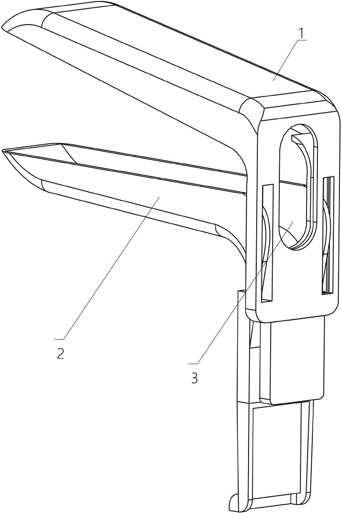
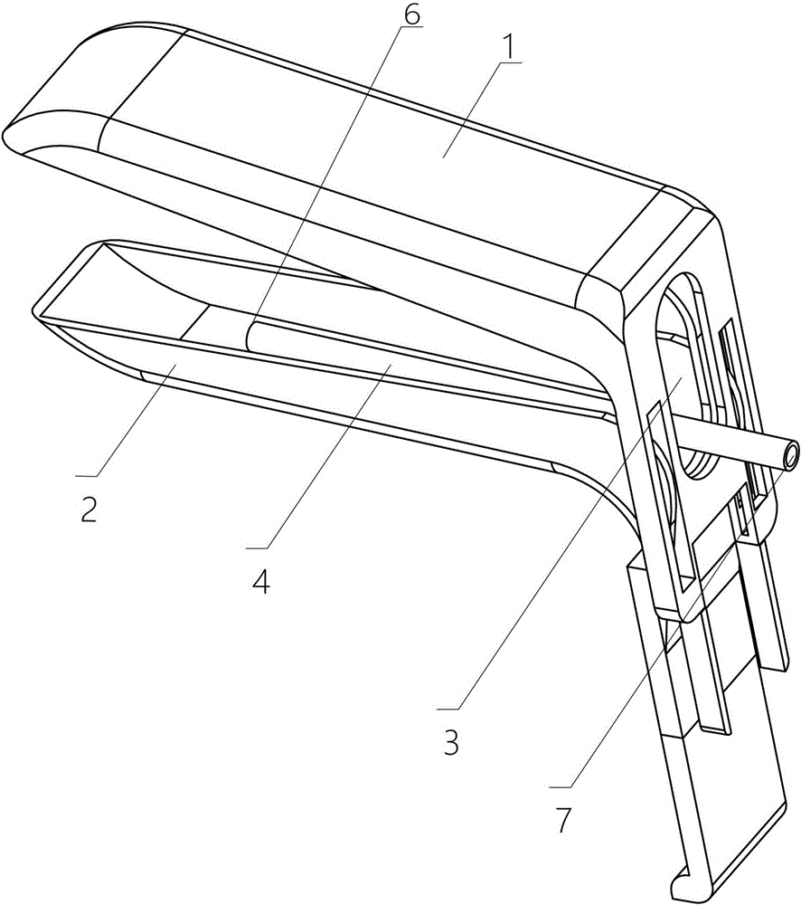
[0042] The first embodiment of the present invention provides a vaginal dilator, see figure 2 As shown, it includes two expansion wings that cooperate with each other, namely an upper expansion wing 1 and a lower expansion wing 2, which can extend into the vagina and are used to open the vagina;
[0043] Wherein, the vaginal dilator further includes a diversion channel 4 for sucking out blood. The head end of the diversion channel 4 is provided with a diversion hole 6 which is located near the front half of the lower expansion wing 2.
[0044] In this embodiment, an observation window 3 is formed where the two expansion wings are connected;
[0045] The diversion channel 4 is a catheter, which extends from the observation window 3 into the vaginal dilator and is fixed above the lower expansion wing 2. When the catheter is connected to the external negative pressure suction device, the catheter set above the lower expansion wing 2 can be used to suck blood exuded from the target tiss...
Embodiment approach 2
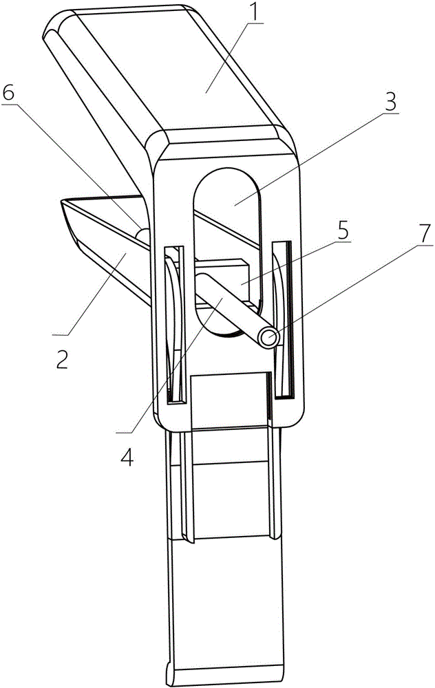
[0049] The second embodiment of the present invention provides a vaginal dilator. The second embodiment is a further improvement of the first embodiment. The main improvement lies in that in the second embodiment of the present invention, see image 3 As shown, the lower expansion wing 2 is provided with a support frame 5, and the support frame 5 is provided with support holes; the catheter is detachably fixed on the support frame 5 through the support holes. The support hole can make the catheter detachable, so the use is more flexible.
[0050] Among them, the support frame 5 can be screwed to the catheter, so as to obtain a better fixing effect.
Embodiment approach 3
[0052] The third embodiment of the present invention provides a vaginal dilator. The third embodiment is different from the first and second embodiments. The main difference is that in the first and second embodiments of the present invention, the diversion channel 4 is a duct; while in the third embodiment of the present invention Way, see Figure 4 As shown, the diversion channel 4 is a cavity laid in the lower expansion wing 2.
[0053] Specifically, when the diversion channel 4 is a cavity laid in the lower expansion wing 2, the diversion hole 6 is opened on the lower expansion wing 2. Make the diversion channel 4 form a cavity inside the lower expansion wing 2, and the diversion channel 4 will not need to occupy the operation space between the upper expansion wing 1 and the lower expansion wing 2, and it will be less obstructive to the operation, so it can further provide more Good surgical vision.
[0054] For the position setting of the diversion hole 6, in this embodiment...
PUM
 Abstract
Description
Claims
Application Information
 - R&D
- Intellectual Property
- Life Sciences
- Materials
- Tech Scout
- Unparalleled Data Quality
- Higher Quality Content
- 60% Fewer Hallucinations
Browse by: Latest US Patents, China's latest patents, Technical Efficacy Thesaurus, Application Domain, Technology Topic, Popular Technical Reports.
© 2025 PatSnap. All rights reserved.Legal|Privacy policy|Modern Slavery Act Transparency Statement|Sitemap|About US| Contact US: help@patsnap.com


