Fire extinguisher fixing rack

A fixed frame and fire extinguisher technology, applied in fire rescue and other directions, can solve problems such as unsafe placement, and achieve the effect of simple structure, stable and safe placement of fire extinguishers

Inactive Publication Date: 2017-05-31
NINGBO YUANFENG FIRE CONTROL EQUIP
View PDF0 Cites 0 Cited by
  • Summary
  • Abstract
  • Description
  • Claims
  • Application Information

AI Technical Summary

Problems solved by technology

[0004] The problem to be solved by the present invention is to provide a fire extinguisher fixing frame to overcome the defect of unsafe placement in the prior art

Method used


Image

  • Fire extinguisher fixing rack

Examples


Embodiment Construction

[0012] The specific implementation manners of the present invention will be further described in detail below in conjunction with the accompanying drawings and embodiments. The following examples are used to illustrate the present invention, but are not intended to limit the scope of the present invention.

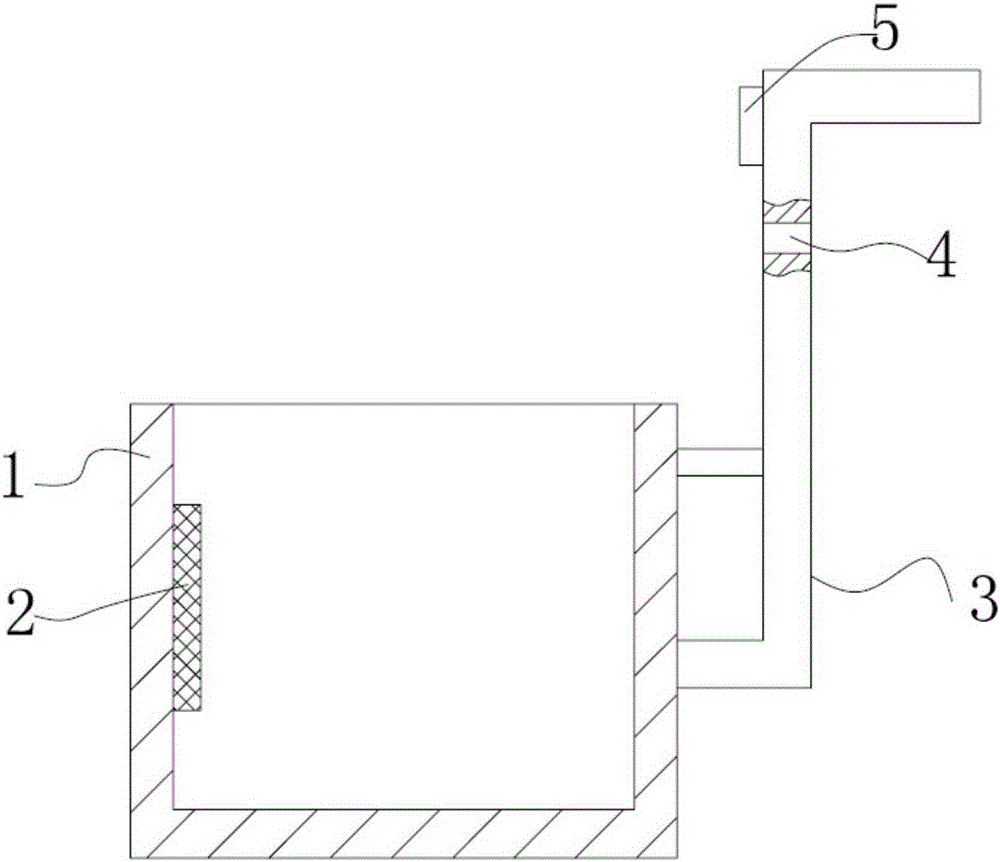
[0013] like figure 1 As shown, a fire extinguisher fixing frame of the present invention includes a cylinder body 1, a buffer pad 2, a connecting rod 3 and a lighting lamp 5; the connecting rod 3 is fixedly connected to the cylinder body 1; the buffer pad 2 is arranged on One side of the inner wall of the cylinder body 1 ; the upper end of the connecting rod 3 is provided with a mounting hole 4 , and the top of the connecting rod 3 is provided with the LED lighting lamp 5 . The barrel 1 is made of stainless steel. The cylinder body 1 is welded and fixed to the connecting rod 3 .

[0014] The fire extinguisher fixing frame of the present invention has a simple structure ...


PUM


Abstract

The invention provides a fire extinguisher fixing rack. The fire extinguisher fixing rack comprises a barrel, a crash pad, a connecting rod and an illuminating lamp. The connecting rod is fixedly connected with the barrel. The crash pad is arranged at one side of the inner wall of the barrel. A mounting hole is formed in the upper end of the connecting rod. The LED illuminating lamp is arranged at the top of the connecting rod. The fire extinguisher fixing rack is simple in structure, and fire extinguishers can be placed stably and safely.

Description

technical field [0001] The invention relates to a fire extinguisher fixing frame. Background technique [0002] A fire extinguisher is a portable fire extinguishing tool. Chemicals are placed in the fire extinguisher to put out the fire. Fire extinguishers are one of the common fire prevention facilities. They are stored in public places or places where fires may occur. Different types of fire extinguishers are filled with different ingredients and are specially designed for different fire alarms. Care must be taken during use to avoid adverse effects and danger. The existing fire extinguisher fixing frame is placed unsafely. Contents of the invention [0003] (1) Technical problems to be solved [0004] The problem to be solved by the present invention is to provide a fire extinguisher fixing frame to overcome the defect of unsafe placement in the prior art. [0005] (2) Technical solution [0006] In order to solve the above technical problem, the present invention...

Claims


Application Information

Patent Timeline
Patent Type & Authority Applications(China)
IPC IPC(8): A62C13/78
Inventor 郑江义
Owner NINGBO YUANFENG FIRE CONTROL EQUIP
Why Eureka
Try Eureka