Real-time propeller blade angle monitoring device

A technology for monitoring devices and propellers, applied to propellers, transportation and packaging, aircraft parts, etc., can solve the problems that propellers cannot be measured in real time and feedback blades in time, and achieve simple structure, convenient installation and disassembly, and simple connection

Pending Publication Date: 2017-05-31
AVIC HUIYANG AVIATION PROPELLER
View PDF0 Cites 3 Cited by
  • Summary
  • Abstract
  • Description
  • Claims
  • Application Information

AI Technical Summary

Problems solved by technology

Because the flight environment of the aircraft is very complex, it is a permanent subject to study the variable pitch control device of the propeller so that it can control the blade angle more accurately and achieve the best output efficiency of the propeller. Therefore, the working propeller blade angle It is necessary to monitor the blade angle constantly and collect the blade angle in time, so as to study the relationship between the blade angle, the propeller speed and the engine power, and then study a better propeller pitch control device. However, the current propellers cannot be measured in real time and Timely feedback of the angle of its blades

Method used


Image

  • Real-time propeller blade angle monitoring device

Examples


Embodiment Construction

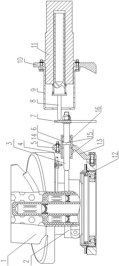
[0011] The present invention will be further described below in conjunction with the accompanying drawings and specific embodiments.

[0012] like figure 1 As shown, this embodiment includes two groups of moving devices, two groups of sensor devices, an intermediate disk, a processor and a display screen. Each group of moving devices includes a cam 2, a push rod I 3 and a support I 4. The two cams 2 are respectively fixed on the roots of the two symmetrical blades 1, and the preferred structure is: the cam 2 is two half-cams; the joint of the two half-cams protrudes from a connecting boss with a bolt mounting hole. It is clamped on the root of the blade 1 and fixed together by bolts and nuts. The ejector rod I 3 is telescopically connected to the support I 4, and one end thereof is supported on the outer circle of the cam 2. The support I 4 is fixed on the propeller hub 12 through the mounting plate 5; its preferred structure is: the mounting plate 5 is fixed on the outer c...


PUM


Abstract

The invention discloses a real-time propeller blade angle monitoring device. The real-time propeller blade angle monitoring device comprises two groups of pushing devices, two groups of sensor devices, an intermediate disc, a processor and a display screen, wherein each group of pushing devices comprises a cam, an ejector rod I and a support I; each group of sensor devices comprises an ejector rod II, a support II and a displacement sensor; the two cams are respectively fixed on blade roots of two symmetric propeller blades; the ejector rod I are connected with the support I in a telescopic manner; one ends of the ejector rod I are pushed against outer circles of the cams; the supports I are fixed on propeller hubs; the intermediate disc sleeves a propeller shaft; the other end of each ejector rod I is fixed at the outer edge of the intermediate disc; the supports II and the displacement sensors are fixed in the same position of an engine shell; the ejector rods II are connected with the supports II in a telescopic manner; one ends of the ejector rods II are connected with contacts of the displacement sensors; and the other ends of the ejector rods II are pushed against the outer edge of the intermediate disc. The real-time propeller blade angle monitoring device can measure the angle of a propeller blade at any time and feed back the angle of the propeller blade in time, has the advantages of simple and reliable structure, convenient mounting and detaching and accurate propeller blade angle measurement, and can realize on-site maintenance and replacement.

Description

technical field [0001] The invention relates to a device for constantly monitoring the blade angle of a propeller. Background technique [0002] The propeller pitch control device is to control the propeller to work at the best blade angle under various working conditions of the engine and the aircraft, so as to achieve the best working efficiency of the propeller. Because the flight environment of the aircraft is very complicated, it is a permanent subject to study the variable pitch control device of the propeller so that it can control the blade angle more accurately and achieve the best output efficiency of the propeller. Therefore, the working propeller blade angle It is necessary to monitor the blade angle from time to time and collect the blade angle in time, so as to study the relationship between the blade angle and the propeller speed and engine power. It is necessary to study a better propeller pitch control device, but the current propellers cannot be measured in...

Claims


Application Information

Patent Timeline
Patent Type & Authority Applications(China)
IPC IPC(8): B64C11/30
CPCB64C11/301
Inventor 王金利夏玉刚张聪莉蔡猛
Owner AVIC HUIYANG AVIATION PROPELLER
Why Eureka
Try Eureka