
Lightweight shock isolation device of actuating mechanism on satellite

A light and handy technology for actuators, applied in the field of vibration isolation devices for lightweight on-board actuators, can solve problems such as lightening, achieve broad application prospects, facilitate maintenance and replacement, and reduce production costs

Active Publication Date: 2017-05-31
CHINA ACADEMY OF SPACE TECHNOLOGY
View PDF6 Cites 4 Cited by
  • Summary
  • Abstract
  • Description
  • Claims
  • Application Information

AI Technical Summary

Problems solved by technology

[0006] The technical problem solved by the present invention is: to overcome the deficiencies of the prior art, the present invention provides a light-weight planetary actuator vibration isolation device, by installing actuators in different hinged ways between the upper platform and the lower platform, The installation configuration of the control moment gyro has been changed, and the singular problem of the control moment gyro group has been overcome; through the cooperation of movable elements, vibration isolation elements and sensors, the structure of the actuator has been optimized, and the problem of actuators with high-speed rotors has been solved. Vibration disturbance problem; through the mutual cooperation of the three actuators, the weight of the vibration isolation device is reduced, which makes up for the bulky and complicated defects of the traditional vibration isolation device

Method used


Image

  • Lightweight shock isolation device of actuating mechanism on satellite
  • Lightweight shock isolation device of actuating mechanism on satellite
  • Lightweight shock isolation device of actuating mechanism on satellite

Examples


Embodiment Construction

[0028] In order to make the solution of the present invention clearer, the present invention will be further described below in conjunction with the accompanying drawings and specific embodiments:

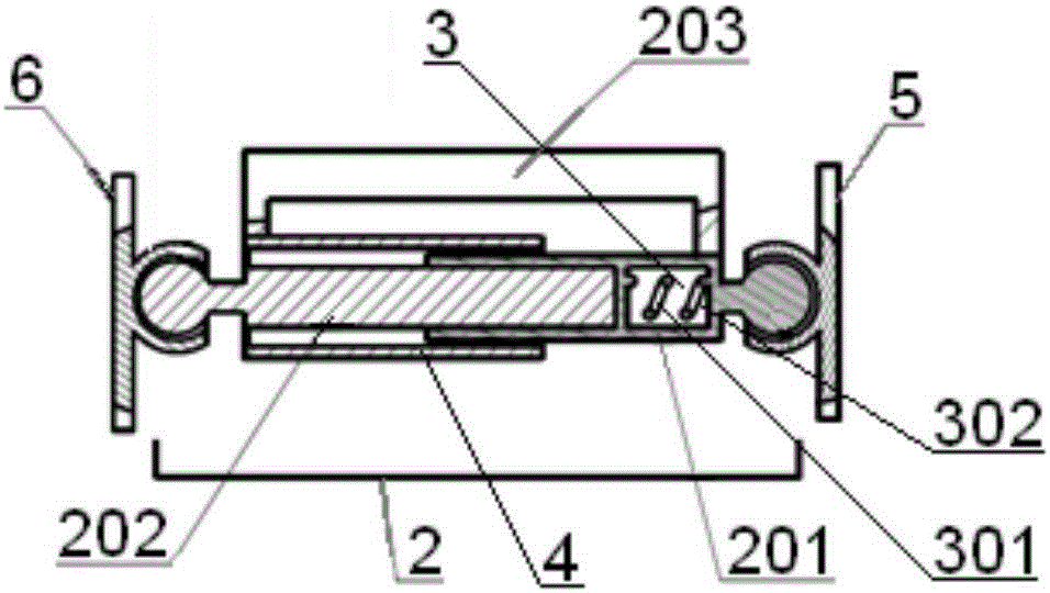
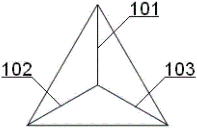
[0029] Such as Figure 1~3 As shown in Fig. 1, a light-weight on-board actuator vibration isolation device includes an actuator 1, an upper platform 5 and a lower platform 6; one side of the upper platform 5 is fixedly connected with the disturbance source, and the other side of the upper platform 5 is connected One end of the actuator 1 is hinged, the other end of the actuator 1 is hinged to one side of the lower platform 6, the other side of the lower platform 6 is fixedly connected to the satellite, the upper platform 5 is parallel to the lower platform 6, and the number of actuators 1 is set to three. The three actuators 1 are jointly hinged at one point on the upper platform, the vertical projection of the center of mass of the disturbance source on the upper platform coincide...


PUM


Abstract

The invention discloses a lightweight shock isolation device of an actuating mechanism on a satellite. The light shock isolation device of the actuating mechanism on the satellite comprises actuators, an upper platform and a lower platform. The upper platform and the lower platform are parallel to each other, and are fixedly connected with a vibration disturbance source and the satellite correspondingly. The three actuators are arranged between the upper platform and the lower platform, and the three actuators are hinged to the same point on the upper platform. The vertical projection of the mass center of the vibration disturbance source coincides with the hinged point of the three actuators on the upper platform. The three actuators are hinged to three points on the lower platform correspondingly, and connections of the three points form an equilateral triangle. The vertical projection of the mass center of the vibration disturbance source on the lower platform coincides with the center of the equilateral triangle. By mounting the actuators in different hinged ways, the mounting configuration of a control moment gyro is changed, and the singular difficulty of a control moment gyro group is overcome; through cooperation of a movable component, a shock isolation component and a sensor, the vibration disturbance problem of the actuating mechanism with high-speed rotors is solved; and the light shock isolation device of the actuating mechanism on the satellite has the characteristics of miniaturization and intellectualization.

Description

technical field [0001] The invention relates to a lightweight on-board actuator vibration isolation device, which is especially suitable for vibration suppression of a control moment gyroscope group with singularity in the attitude control process, and belongs to the vibration isolation technical field of high-speed rotor disturbance source actuators. Background technique [0002] Optical loads installed on high-resolution satellites are generally very sensitive to vibration, and actuators such as flywheels with high-speed rotors and control moment gyroscopes are one of the most important sources of disturbance on the satellite. [0003] During the on-orbit operation of actuators with high-speed rotors such as flywheels and control moment gyroscopes, disturbances containing various simple harmonic vibration components will be generated. Stand-alone product for measurement accuracy. For satellites that need to quickly maneuver from one target to another, complete a large num...

Claims


Application Information

Patent Timeline
IPC IPC(8): B64G1/22
CPCB64G1/22B64G1/228
Inventor 崔颖慧范为姚延风李东泽黄华刘波裴胜伟
Owner CHINA ACADEMY OF SPACE TECHNOLOGY
Learn More