Power Converter and Its Control Method and Air Conditioner

a power converter and control method technology, applied in the direction of process and machine control, instruments, heat measurement, etc., can solve the problems of increased loss, especially large size of reactors and capacitors, heavy weight, etc., to reduce high-frequency disturbance, stably apply output voltage, and rotate the motor stably

Active Publication Date: 2009-04-23
DAIKIN IND LTD
View PDF10 Cites 7 Cited by
  • Summary
  • Abstract
  • Description
  • Claims
  • Application Information

AI Technical Summary

Benefits of technology

[0033]According to any of the first, fourth, fifth and eighth aspects of the power converter of the present invention, or according to any of the first, fourth, fifth and eighth aspects of the power converter controlling method, the second load consumes a high-frequency component contained in the first current with respect to the fundamental frequency of the input current, which makes it possible to suppress the high-frequency component of the input current to the rectifier circuit and to suppress high-frequency disturbance to the alternating-current power supply.
[0034]According to the second or sixth aspect of the power converter of the present invention, or according to the second or sixth aspect of the power converter controlling method, it is possible to stably apply the output voltage to the second load.
[0035]

Problems solved by technology

The reactor and capacitor are especially large-sized and heavy-weighted among the parts of

Method used


Image

  • Power Converter and Its Control Method and Air Conditioner
  • Power Converter and Its Control Method and Air Conditioner
  • Power Converter and Its Control Method and Air Conditioner

Examples


first preferred embodiment

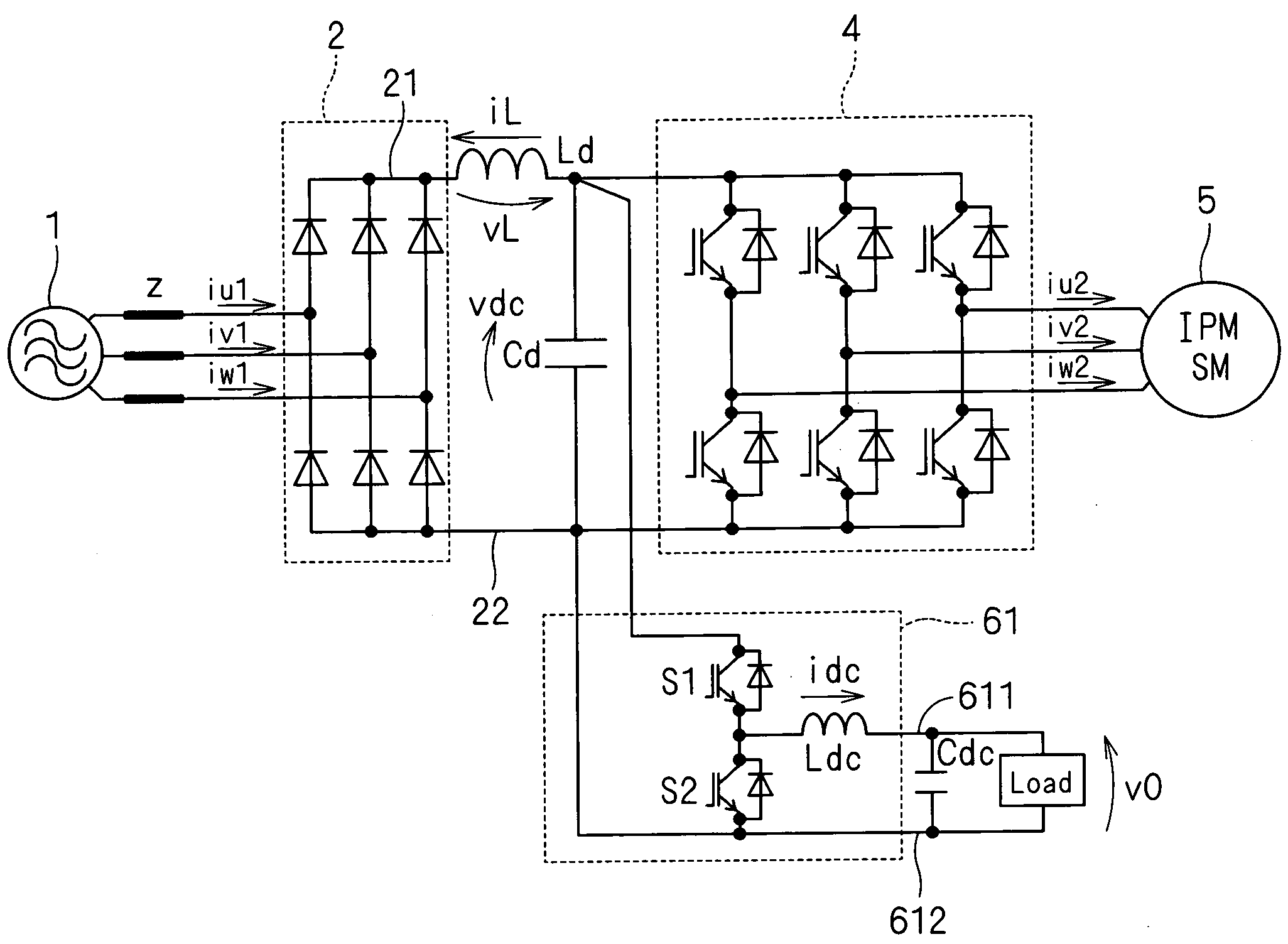
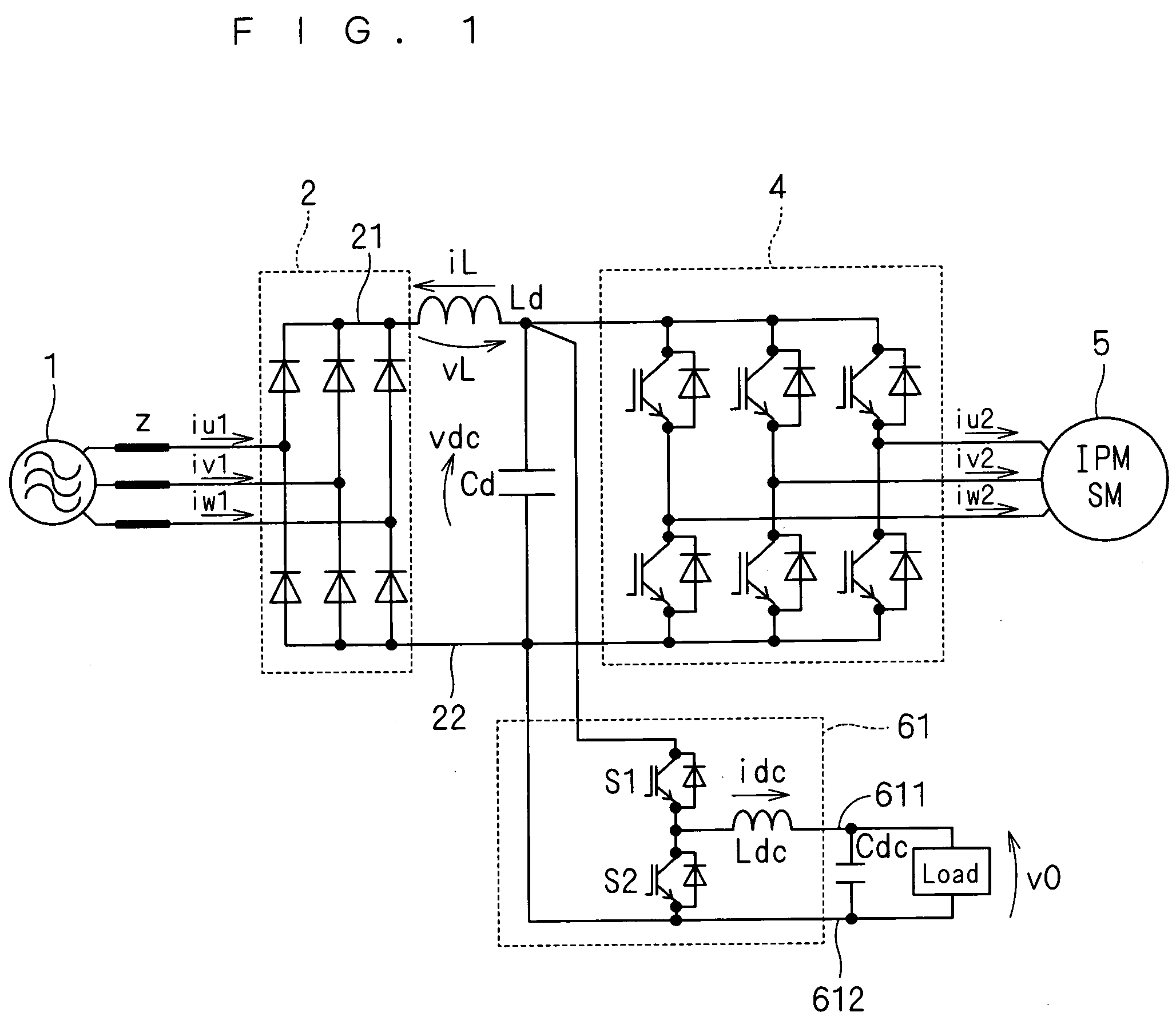
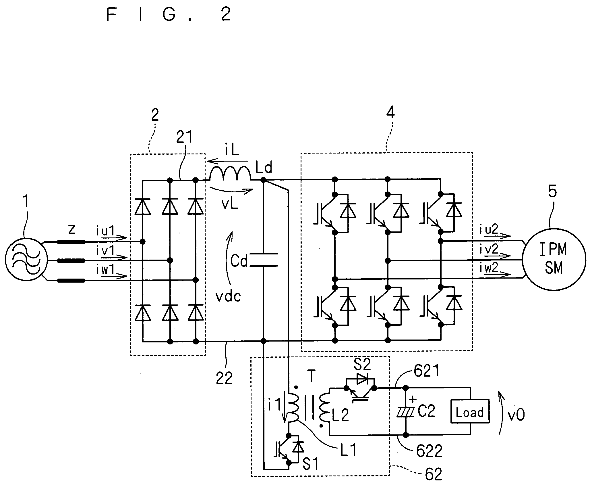
[0062]FIGS. 1 and 2 each conceptually illustrate a power converter according to this preferred embodiment. The power converters each include a first power-supply line 21, a second power-supply line 22, a rectifier circuit 2, a capacitor Cd, a reactor Ld, an inverter 4, and a switching power-supply circuit 61 (or a switching power-supply circuit 62).

[0063]FIGS. 1 and 2 show an ac power supply 1 that supplies power to the power converter, and a motor 5 that is supplied with the output from the inverter 4. Also, FIG. 1 shows a capacitor Cdc and a driven part Load that are supplied with the output of the switching power-supply circuit 61, and FIG. 2 shows a capacitor C2 and a driven part Load that are supplied with the output of the switching power-supply circuit 62. The capacitor Cdc or C2 smoothes the output of the switching power-supply circuit 61 or 62 and supplies it to the driven part Load. This preferred embodiment adopts a three-phase alternating-current power supply as the ac p...

second preferred embodiment

[0103]FIG. 9 conceptually illustrates a power converter according to this preferred embodiment. In this power converter, a first power-supply line 21, a second power-supply line 22, a rectifier circuit 2, a capacitor Cd, a reactor Ld, and an inverter 4 are configured in the same way as those of the power converter of the first preferred embodiment, and a switching power-supply circuit 6 is connected between the first power-supply line 21 and the second power-supply line 22. FIG. 9 shows an ac power supply 1 and a motor 5 as in FIGS. 1 and 2, and it further shows a motor 7 that is supplied with the output of the switching power-supply circuit 6. With the load formed of the inverter 4 and the motor 5 being regarded as a first load 4+5, the motor 7 can be regarded as a second load.

[0104]The switching power-supply circuit 6 is a three-phase inverter and has switches S31 to S36. In this preferred embodiment, IGBT modules are adopted as the switches S31 to S36. In general, a three-phase i...

third preferred embodiment

[0125]FIG. 15 illustrates a configuration in which a single-phase alternating-current power supply is adopted as the ac power supply 1 in the power converter shown in FIG. 1. In this case, the rectifier circuit 2 rectifies an input current ic from the ac power supply 1 and outputs direct-current voltage between the first power-supply line 21 and the second power-supply line 22. In other respects, it is configured in the same way as the power converter shown in FIG. 1.

[0126]Also with this power converter, performing control in the same way as described in the first preferred embodiment offers the same effects.

[0127]FIG. 16 is a graph illustrating the time variation of the input current ic that is exhibited when the control of this preferred embodiment is performed. FIG. 17 is a graph illustrating the time variation of the voltage vdc that is exhibited when the control of this preferred embodiment is performed. For comparison with FIGS. 16 and 17, FIGS. 18 and 19 respectively show the...


PUM


Abstract

A controller (10) includes subtracters (101, 105), a command value corrector (103), and a control block (102). The subtracter (101) obtains a deviation (Δv0) of an output voltage (v0) applied from a switching power-supply circuit (61) to a second load (Cdc+Load) with respect to its command value (v0*). The control block (102) performs PI control on the basis of the deviation (Δv0) to generate a command value (idc*) for a current (idc) flowing in a coil (Ldc). The command value corrector (103) corrects the command value (idc*) such that high-frequency components of a current (iL) flowing in a first power-supply line (21), with respect to the fundamental frequency of an input current (iu1, iv1, iw1), are consumed in the switching power-supply circuit (61). The subtracter (105) obtains a deviation (Δidc) between the corrected command value (idc*) and the current (idc). Commands (r1, r2) for switches are generated on the basis of the deviation (Δidc).

Description

TECHNICAL FIELD[0001]The present invention relates to a power converter and its control method, and particularly to a power converter of a type commonly called “capacitor-less” and its control method.BACKGROUND ART[0002]An air conditioner includes a motor for a refrigerant compressor, and a power converter for supplying desired power to the motor. A common power converter includes a converter, an inverter, and a smoothing capacitor between them, and converts power supplied from an alternating-current power supply. Also, a reactor is provided to improve the input power factor. For example, the inductance of the reactor is about 2 mH, and the capacitance of the capacitor is about 2000 μF.[0003]The reactor and capacitor are especially large-sized and heavy-weighted among the parts of the power converter. Also, they constitute a cause of increased loss due to heat generation.[0004]Accordingly, a technique is proposed in which the capacitance of the capacitor is reduced to downsize the c...

Claims


Application Information

Patent Timeline
IPC IPC(8): H02J3/00
CPCH02M5/458H02M1/12
Inventor HAGA, HITOSHI
Owner DAIKIN IND LTD
Why Eureka
Try Eureka