Annular seamless transition type vehicle speed reduction device
A deceleration device, seamless technology, applied in the direction of roads, buildings, road signs, etc., can solve the problems of easy scratching, vehicle bumping, and reducing the driver's driving comfort.
- Summary
- Abstract
- Description
- Claims
- Application Information
AI Technical Summary
Problems solved by technology
Method used
Image

Examples
Embodiment Construction
[0025] The vehicle deceleration equipment provided by the present invention can carry out adaptive lifting adjustment according to the driving speed of the vehicle, so as to maintain the blocking posture when the vehicle passes at high speed, reduce the comfort of the driver, and reduce the vehicle speed. When passing at an hourly speed or slowly, the barrier can be gradually eliminated, and the vehicle with a lower chassis can be allowed to pass, and the design is more humanized; in addition, the medium in the present invention refers to a liquid or gas with good flow properties, such as air, carbon dioxide, water, hydraulic oil, etc.
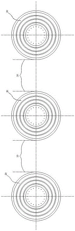
[0026] See attached figure 1 , a number of deceleration devices are evenly spaced along the width direction of the road, and a barrier-free area 10 is formed between adjacent deceleration devices. Usually, the length of the barrier-free area 10 should be slightly greater than the vehicle width; the size limit of the barrier-free area 10, The ...
PUM
 Abstract
Description
Claims
Application Information