Unlock instant, AI-driven research and patent intelligence for your innovation.
A triangular keel installation structure for a building suspended ceiling
What is Al technical title?
Al technical title is built by PatSnap Al team. It summarizes the technical point description of the patent document.
A technology of triangular keel and installation structure, which is applied to building components, building structures, buildings, etc., can solve the problems of high height, inconvenient installation and construction, complex structure, etc., and achieves simple installation process, convenient installation and construction, and reduced spacing. Effect
Inactive Publication Date: 2019-05-24
杨海丽
View PDF6 Cites 2 Cited by
Summary
Abstract
Description
Claims
Application Information
AI Technical Summary
This helps you quickly interpret patents by identifying the three key elements:
Problems solved by technology
Method used
Benefits of technology
Problems solved by technology
[0003] The problems of this kind of suspended ceiling are: first, the structure is complicated, and installation and construction are inconvenient; second, the height is relatively large, so it is not suitable for low-rise buildings.
Method used
Image
Click on the blue label to locate the original text in one second.
Reading with bidirectional positioning of images and text.
Examples
Embodiment 1
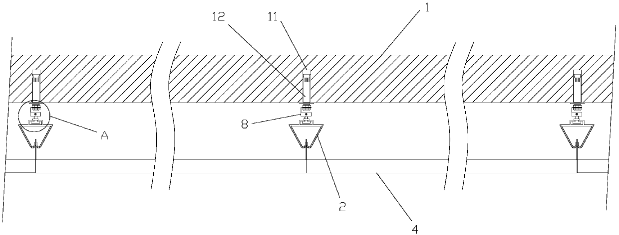
[0062] Such as figure 2 , 3 As shown in , 4, the triangular keel installation structure of the architectural suspended ceiling described in this embodiment includes several triangular keels 2 arranged at intervals below the ceiling 1, and a gusset 4 is clamped below the triangular keel 2, and is characterized in that:
[0063] Such as Figure 6 As shown, the top of the triangular keel 2 has a narrow slot 22 formed by two oppositely arranged L-shaped ribs 21;
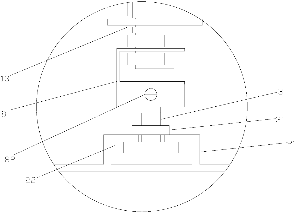
[0064] Such as Figure 7 , 8 Shown, be provided with some screw rods 3 in the narrow mouth groove 22, the screw rod head of screw rod 3 is limited in the narrow mouth groove 22, and rod body passes through the narrow mouth groove 22; The tight nut 31 is located above the narrow slot 22 and has a width greater than the opening of the narrow slot 22, and the top of the screw rod 3 is provided with a first connecting hole 32;
[0065] Such as Figure 5 As shown, there are several rows of installation holes 11 on the ...
Embodiment 2
[0078] Such as Figure 9 , 10 As shown, the triangular keel installation structure of the building ceiling described in this embodiment is different from Embodiment 1 in that the structure of the expansion connector 12 is different, that is, the expansion connector 12 includes an expansion tube 5, a core rod 6 , lifting assembly 7 and connection part 8;
[0079] Such as Figure 11 As shown, the expansion tube 5 is embedded in the installation hole 11 on the ceiling 1. The expansion tube 5 includes an upper tube body 51 and a lower tube body 52 nested together. A ring of expansion tubes is provided on the top of the upper tube body 51. A gap 54 is provided between two adjacent expansion legs 53, and a first reaming hole 55 is provided at the inner bottom of the lower tube body 52;
[0080] Such as Figure 12 , 13 As shown, the core rod 6 passes through the expansion tube 5, and the top of the core rod 6 is an expansion head 61, which is located inside the expansion foot 53...
PUM
Abstract
The invention discloses a triangular keel mounting structure of a building suspended ceiling. The triangular keel mounting structure comprises triangular keels. Buckling plates are mounted on the lower portions of the triangular keels in a clamped mode. The tops of the triangular keels are provided with narrow-mouth grooves which are internally provided with a plurality of screws. The ceiling is provided with a plurality of mounting holes which are internally provided with expansion type connecting components. The expansion type connecting components comprise connecting parts which are provided with second connecting holes. The tops of the screws are inserted into the connecting parts. First connecting holes and the second connecting holes are connected through connecting elements. The triangular keel mounting structure has the beneficial effects that the slidable screws in the narrow-mouth grooves are connected with the expansion type connecting parts, the mounting processes of a hanger rod and a main keel are omitted, the mounting distance between the hanger rod and the main keel is omitted, and therefore, the triangular keel mounting structure has the characteristics that mounting is convenient, and meanwhile, the distance between the ceiling and the buckling plates is remarkably decreased; and the triangular keel mounting structure is suitable for residences of low floor height. The invention further provides a construction method of the triangular keel mounting structure of the building suspended ceiling.
Description
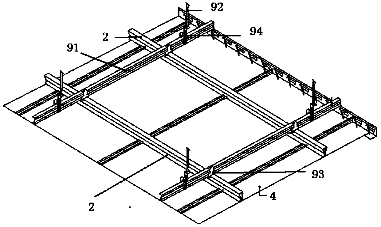
technical field [0001] The invention relates to a building suspended ceiling structure, in particular to a triangular keel installation structure and a construction method of a building suspended ceiling. Background technique [0002] Such as figure 1 As shown, in the existing suspended ceiling, the triangular keel 2 is used to clamp the lower gusset 4 (the upper parts of the gusset 4 have edges that can be snapped into the triangular keel 2), and the triangular keel 2 is connected to the main keel 91 , the main keel 91 and the triangular keel 2 are vertically distributed in space, the main keel 91 is connected to the suspender 92 by means of the main keel hanger 94, and the suspender 92 is connected to the expansion screw on the ceiling. [0003] The problem that this kind of suspended ceiling exists is: first, the structure is complicated, and installation and construction are inconvenient; Second, the height is relatively large, and it is not suitable for low-rise buildi...
Claims
Application Information
Patent Timeline
Application Date:The date an application was filed.
Publication Date:The date a patent or application was officially published.
First Publication Date:The earliest publication date of a patent with the same application number.
Issue Date:Publication date of the patent grant document.
PCT Entry Date:The Entry date of PCT National Phase.
Estimated Expiry Date:The statutory expiry date of a patent right according to the Patent Law, and it is the longest term of protection that the patent right can achieve without the termination of the patent right due to other reasons(Term extension factor has been taken into account ).
Invalid Date:Actual expiry date is based on effective date or publication date of legal transaction data of invalid patent.

