Intelligent lock

A smart lock and panel technology, applied in the field of smart locks, can solve problems such as poor positioning effect, excessive force, and failure to meet customer needs, and achieve the effects of improving service life, convenient use, and good positioning effect

Active Publication Date: 2017-05-31
坚士锁业有限公司
View PDF8 Cites 1 Cited by
  • Summary
  • Abstract
  • Description
  • Claims
  • Application Information

AI Technical Summary

Problems solved by technology

[0002] At present, smart locks generally adopt a sliding cover structure, usually using a guide rail design. When the sliding cover moves up and down along the guide rail, it needs to provide an external force to push the sliding cover. The service life of the cover, at the same time, the ordinary smart lock has only two positioning structures, and the positioning

Method used


Image

  • Intelligent lock
  • Intelligent lock
  • Intelligent lock

Examples


Embodiment Construction

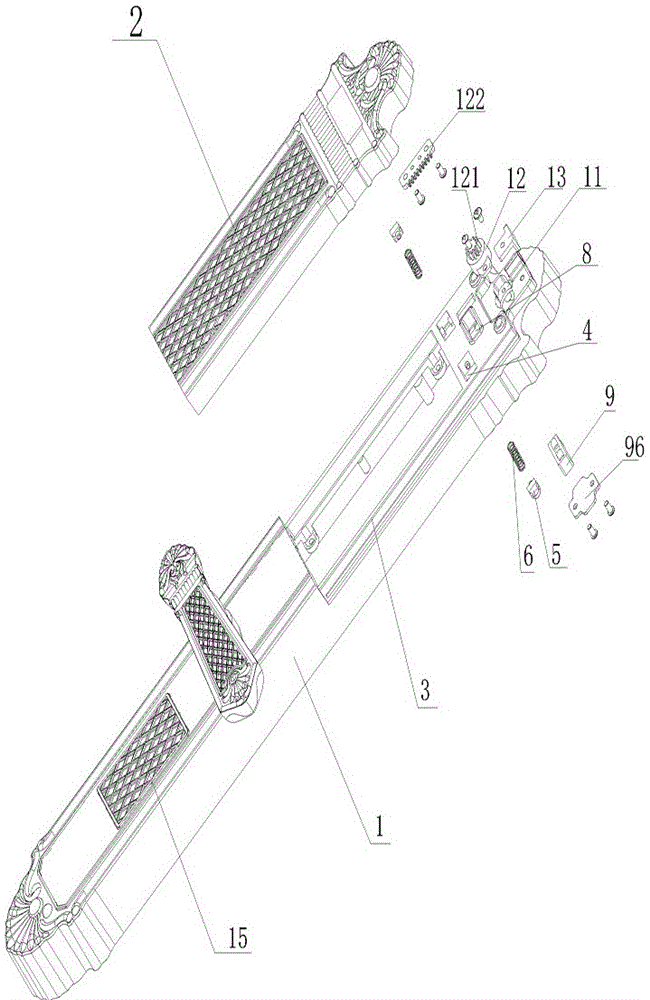
[0022] The accompanying drawings show the technical solution of the present invention and its embodiments, and the relevant details and working principles of the embodiments will be further described below in conjunction with the accompanying drawings.

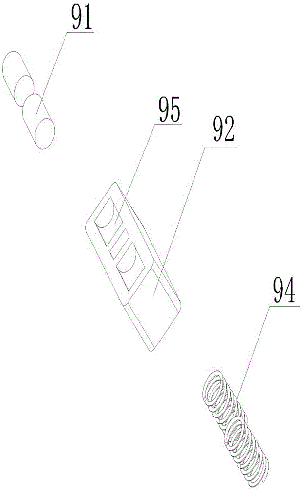
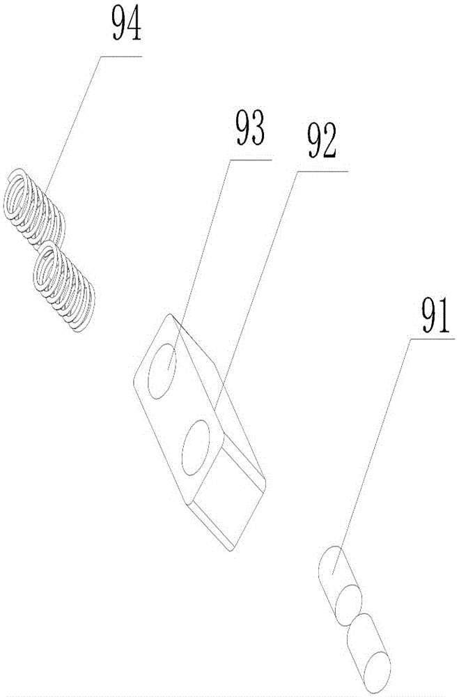
[0023] refer to figure 1 , figure 2 As shown, a smart lock includes a panel, the panel includes a panel body 1 and a slide cover 2, the panel body has a guide rail 3, the slide cover 2 is socketed with the guide rail 3 and moves up and down along it, the panel body The upper end is provided with two symmetrical grooves 4, the end of the arc guide block 5 is sleeved in the groove 4, and an elastic device 6 is arranged between the arc guide block 5 and the end of the groove 4, and the sliding cover 2 There are symmetrical arc-shaped grooves 7 on both sides of the lower end, and a first opening 8 is opened on the upper end of the panel body, and a roller device 9 is installed in the first opening 8, and the roller device 9 incl...


PUM


Abstract

The invention discloses an intelligent lock. The intelligent lock comprises a panel, wherein the panel comprises a panel body and a sliding cover; the panel body is provided with a guide rail; the sliding cover is connected with the guide rail in a sleeving manner and moves up and down along the guide rail; two symmetrical grooves are formed in the upper end part of the panel body; the end part of each arc surface guide block is connected to the corresponding groove in a sleeving manner; an elastic device is arranged between each arc surface guide block and the end part of the corresponding groove; symmetrical arc-shaped grooves are formed in two sides of the lower end of the sliding cover; a first opening is formed in the upper end part of the panel; a rolling shaft device is mounted in the first opening; a rib is arranged in a position corresponding to the rolling shaft device of the sliding cover; first limiting slots are formed in the rib; and a second limiting slot is formed in the lower end of the rib. According to the intelligent lock disclosed by the invention, basic functions are met, and according to specific requirements of a customer, functions except the basic functions required by the customer are added; and besides, the sliding cover and the panel body of the intelligent lock adopt a three-point positioning manner, so that the positioning effect is good.

Description


Claims


Application Information

Patent Timeline
Owner 坚士锁业有限公司
Why Eureka
Try Eureka