An Experimental Device for the Visual Study of Microwave Plasma-Assisted Ignition

A technology of microwave plasma and assisted ignition, applied in engine ignition, spark ignition controller, spark plug, etc., can solve the problems of increasing heat transfer loss, blocking the light path, and small space for integrating spark plugs, achieving small shading area and heat loss. Small, easy-to-see effects

Active Publication Date: 2018-11-02
HUAZHONG UNIV OF SCI & TECH
View PDF5 Cites 4 Cited by
  • Summary
  • Abstract
  • Description
  • Claims
  • Application Information

AI Technical Summary

Problems solved by technology

[0010] (1) Due to the narrow space between the ground electrode and the positive electrode of the integrated spark plug, the free development of the spherical flame is limited;
[0011] (2) Since Schlieren and other technologies are basically flat light shooting, the cylindrical part of the integrated spark plug and the "L"-shaped ground electrode will block the optical path;
[0012] (3) The cylindrical part of the integrated spark plug and the "L"-shaped ground electrode are relatively large in size, which will increase the heat transfer loss and weaken the effect of microwave energy on the plasma

Method used


Image

  • An Experimental Device for the Visual Study of Microwave Plasma-Assisted Ignition
  • An Experimental Device for the Visual Study of Microwave Plasma-Assisted Ignition
  • An Experimental Device for the Visual Study of Microwave Plasma-Assisted Ignition

Examples


Embodiment Construction

[0035] In order to make the object, technical solution and advantages of the present invention clearer, the present invention will be further described in detail below in conjunction with the accompanying drawings and embodiments. It should be understood that the specific embodiments described here are only used to explain the present invention, not to limit the present invention. In addition, the technical features involved in the various embodiments of the present invention described below can be combined with each other as long as they do not constitute a conflict with each other.

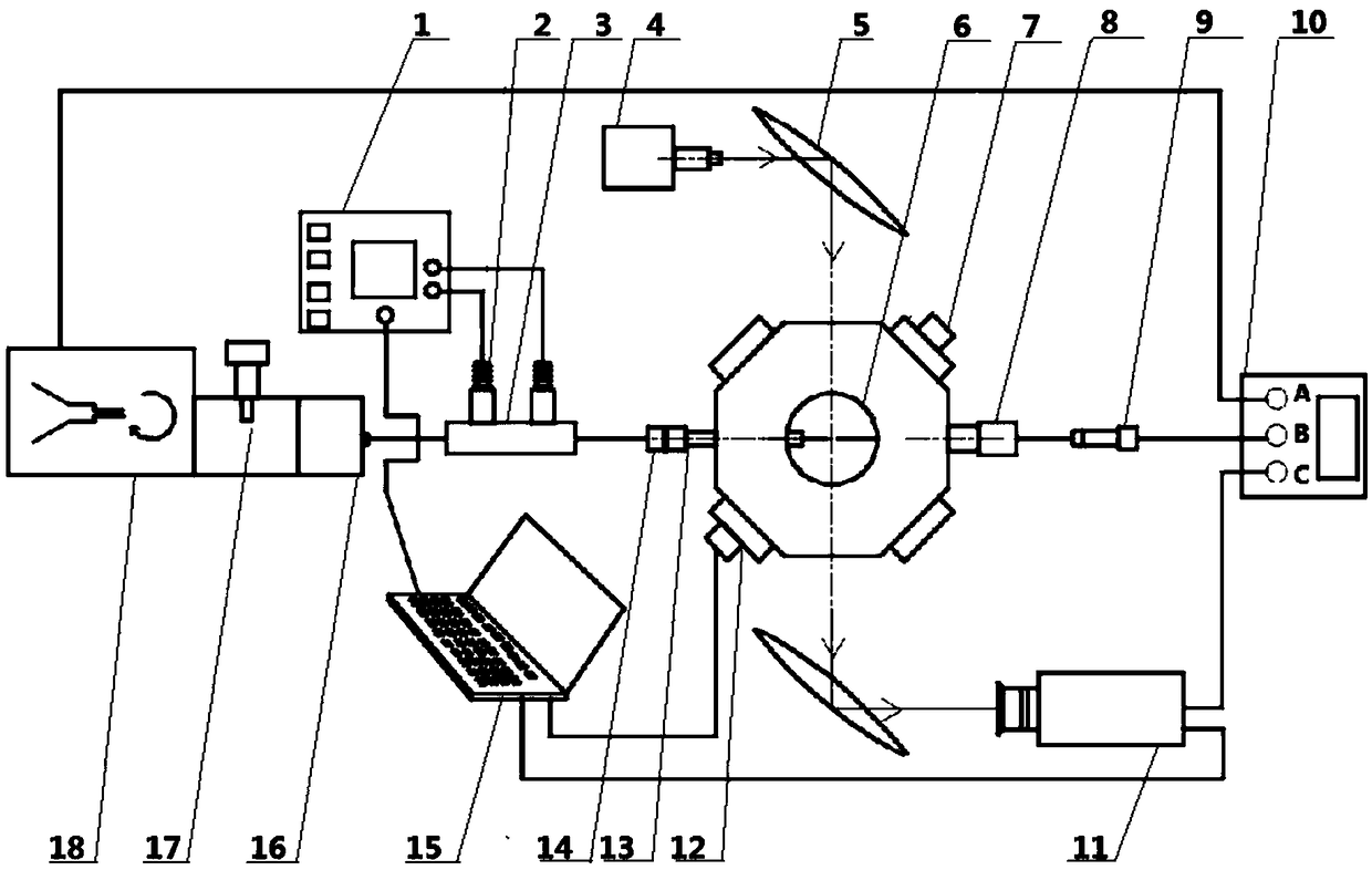
[0036] figure 1 It is a schematic diagram of an experimental device for visually studying microwave plasma-assisted ignition according to an embodiment of the present invention. Such as figure 1 As shown, the device includes a spark plug system, a microwave system, a constant volume incendiary bomb system, an optical photography system, and a control system.

[0037] The control system sends ou...


PUM


Abstract

The invention discloses an experimental device for visual research of microwave plasma assistant ignition. The experimental device comprises a spark plug system, a microwave system, a constant volume napalm bomb system, an optical photographing system and a control system; and the control system sends out three synchronous pulse signals with specific phase differences, wherein the first pulse signal triggers the spark plug system to generate high voltage pulses for discharging and breaking down rarefied mixed fuel gas to form an initial plasma group; the second pulse signal triggers the microwave system to generate microwave pulses with specific frequency and specific power to couple energy in the plasma group so as to expand the plasma group to realize ignition; and the third pulse signal triggers the optical system to penetrate through a quartz window of the constant volume napalm bomb system to be focused on a microwave antenna and a high-voltage electrode center so that the optical photographing system can start photographing and record the whole process of the experiment. According to the experimental device, the ignition mode of a microwave integrated spark plug is reserved, and the action process of microwave plasma assistant ignition can be truly reflected.

Description

technical field [0001] The invention relates to the field of plasma-assisted ignition and combustion, and more particularly relates to an experimental device for visually researching microwave plasma-assisted ignition. Background technique [0002] With the deterioration of the environment and the advanced consumption of energy, the protection of the environment and the efficient use of energy have become more and more personal demands of human beings. Engine researchers are also constantly exploring "energy saving and emission reduction" technologies. Lean combustion technology uses high air-fuel ratio and high compression ratio to improve fuel economy and exhaust emission level. It is one of the most potential combustion methods in the field of internal combustion engines to improve the thermal efficiency of internal combustion engines. However, when the internal combustion engine achieves lean combustion or even ultra-lean combustion, there are problems such as difficulty...

Claims


Application Information

Patent Timeline
Patent Type & Authority Patents(China)
IPC IPC(8): F02P17/00H01T13/20H01T13/32
CPCF02P17/00H01T13/20H01T13/32
Inventor 王兆文张新华武文杰成晓北
Owner HUAZHONG UNIV OF SCI & TECH
Why Eureka
Try Eureka