
Hydraulic quick discharge valve for monorail crane braking oil cylinder

A technology of brake oil cylinder and monorail crane, applied in the field of hydraulic valve, can solve the problems of long connecting oil pipe, long time to return to the oil tank, delay in braking of monorail crane, etc. moving effect

Active Publication Date: 2017-05-31
CHANGZHOU DEV & MFR CENT
View PDF12 Cites 0 Cited by
  • Summary
  • Abstract
  • Description
  • Claims
  • Application Information

AI Technical Summary

Problems solved by technology

One of the important components of the brake device of the monorail crane is the brake cylinder. The working mode of the brake cylinder is spring brake and hydraulic release. One end is connected with a brake pressure block, there is a fixed fulcrum in the middle of the brake lever, and there is a brake spring on the periphery of the brake cylinder, relying on the pre-compression force of the brake spring to push the brake pressure block at the other end of the brake lever to press the guide rail to Realize braking; when the brake is released, the pressure oil enters the rod chamber of each brake cylinder through the brake valve, hydraulic pipeline, joint, etc., and acts on the cylinder piston to overcome the spring force, so that the spring is compressed to release the brake ;During the braking operation, the hydraulic oil in the rod cavity of the brake cylinder needs to be returned to the oil tank of the monorail crane by the hydraulic pipeline, brake valve, etc. The length of the oil pipe is longer, so that the time for the pressure oil in the brake cylinder to flow back to the oil tank through the longer oil pipe is longer, resulting in braking delay in the monorail crane
However, monorail cranes sometimes need to implement emergency and rapid braking in emergency situations. The braking delay phenomenon in the prior art makes it impossible for monorail cranes to quickly brake monorail cranes when emergency braking is required, thereby causing safety accidents. Hidden danger

Method used


Image

  • Hydraulic quick discharge valve for monorail crane braking oil cylinder

Examples


Embodiment 1)

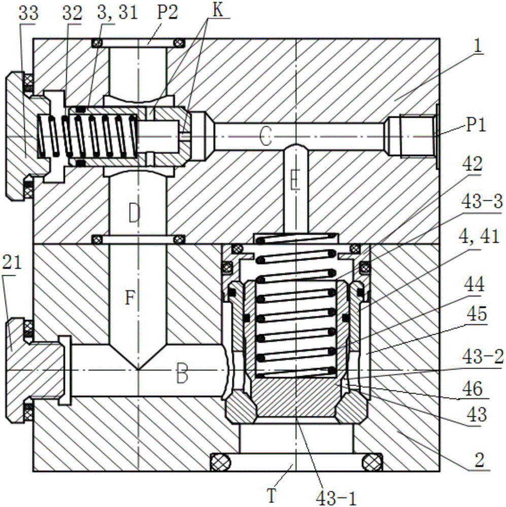
[0023] See figure 1 , The hydraulic quick discharge valve used for the monorail brake cylinder of the present embodiment mainly consists of an upper valve seat 1, a lower valve seat 2, a one-way throttle valve 3 and a plug valve 4.

[0024] The middle part of the right end of the upper valve seat 1 is provided with an oil inlet P1, and the oil inlet P1 is connected to the oil tank of the monorail crane through the oil pipe when in use; The brake cylinders of the suspension are connected to each other for the oil in and out of the brake cylinders; the upper valve seat 1 is provided with a left and right first flow channel C for hydraulic oil circulation, and the right end of the first flow channel C communicates with the oil inlet P1; the upper valve The left part of the seat 1 is provided with a one-way throttle valve installation hole that is the same as the axis line of the first flow channel C; the upper valve seat 1 is provided with a second flow channel D up and down for ...


PUM


Abstract

The invention provides a hydraulic quick discharge valve for a monorail crane braking oil cylinder. The hydraulic quick discharge valve comprises an upper valve seat, a lower valve seat, a one-way throttle valve and a splicing valve, wherein the upper valve seat is provided with an oil inlet, a working port, a first flow channel, a third flow channel communicating with the first flow channel, and a second flow channel communicating with the working port and the one-way throttle valve; the lower valve seat is provided with a quick discharge port, a first flow channel, a second flow channel communicating with the first flow channel, and the splicing valve; the oil inlet and the first flow channel of the upper valve seat, the one-way throttle valve, and the second flow channel and the working port of the upper valve seat construct an oil inlet channel together; the working port and the second flow channel of the upper valve seat, the first flow channel and the second flow channel of the lower valve seat, a valve bush and a valve core of the splicing valve, and the quick discharge port of the lower valve seat construct a pressure oil quick discharge channel. The hydraulic quick discharge valve is simple in structure, and is small in size; during use, pressure oil in the monorail crane braking oil cylinder can be rapidly discharged into an oil tank, thereby meeting the emergency rapid braking demand of a monorail crane.

Description

technical field [0001] The invention relates to the technical field of hydraulic valves, in particular to a hydraulic quick-discharge valve for monorail crane brake cylinders. Background technique [0002] Such as the monorail crane brake device disclosed in the Chinese patent document CN 203111199U with the authorized announcement number, and the monorail crane brake device similar to it, are indispensable components in the coal mine monorail crane. One of the important components of the brake device of the monorail crane is the brake cylinder. The working mode of the brake cylinder is spring brake and hydraulic release. One end is connected with a brake pressure block, there is a fixed fulcrum in the middle of the brake lever, and there is a brake spring on the periphery of the brake cylinder, relying on the pre-compression force of the brake spring to push the brake pressure block at the other end of the brake lever to press the guide rail to Realize braking; when the br...

Claims


Application Information

Patent Timeline
Patent Type & Authority Applications(China)
IPC IPC(8): F15B13/04
CPCF15B13/04F15B2013/002
Inventor 汪达勇马祥宁
Owner CHANGZHOU DEV & MFR CENT
Learn More