A pull-off valve

A technology for pulling off valves and right valve bodies, which is applied in the direction of lifting valves, balance valves, valve devices, etc., and can solve problems such as disconnection or rupture of pipeline interfaces, unstable breaking performance, and breaking accidents, and achieve pull-off Stable performance, achieving sealing and protection, and firm fixation

Active Publication Date: 2019-01-15
CHONGQING LIANGGONG TECH CO LTD
View PDF15 Cites 0 Cited by
  • Summary
  • Abstract
  • Description
  • Claims
  • Application Information

AI Technical Summary

Problems solved by technology

For example, the connection between the movable nozzle and the fixed nozzle is easy to disconnect or rupture the pipeline interface due to sudden overload and external force at the movable nozzle, resulting in fluid leakage, which may cause serious breaking accidents. In response to this problem, the application and promotion of pull-off valves have been developed and have involved many industries. The applicable fields include the output and input of oil tanks and other fixed and mobile fluid storage devices, such as the connection between the fluid delivery arm and the transport carrier.
In terms of function, the breakaway valve products currently used in various industries require that the ultimate goal of the breakaway valve is to avoid and prevent the occurrence of breakaway accidents or minimize the probability of high-risk accidents. The breaking performance, the sealing performance after breaking, reliability and stability are high; however, the breakaway valve in the prior art has the problems of complex structure, high cost and unstable breaking performance

Method used


Image

  • A pull-off valve
  • A pull-off valve

Examples


Embodiment Construction

[0020] In order to make the object, technical solution and advantages of the present invention clearer, the present invention will be further described in detail below in conjunction with the accompanying drawings.

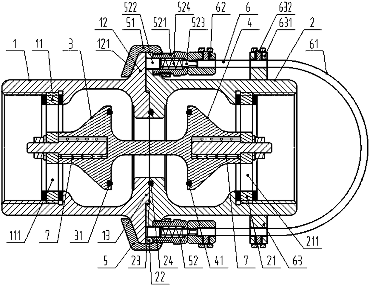
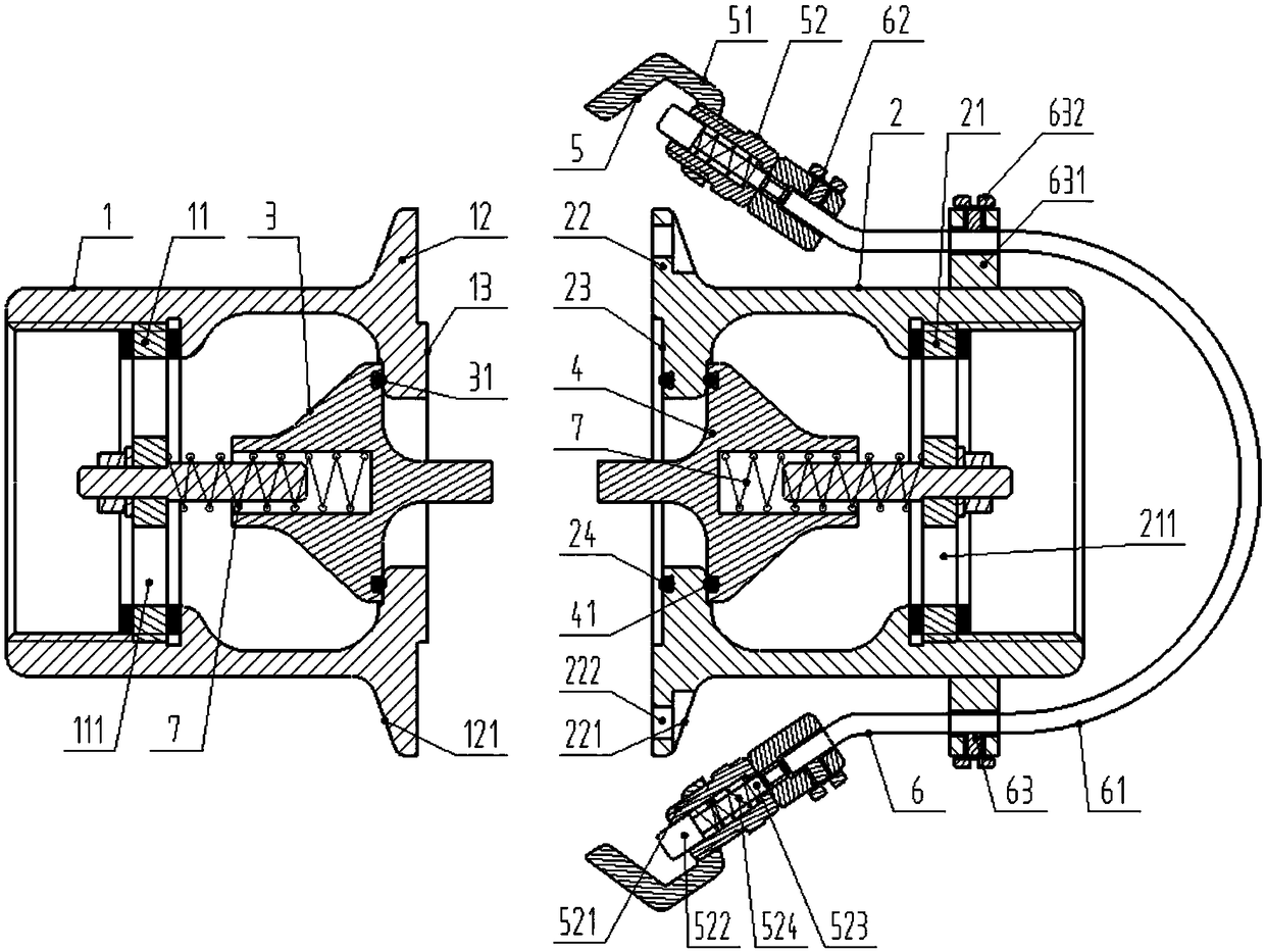
[0021] like Figure 1-2 As shown, a pull-off valve includes a left valve body 1, a right valve body 2, a left valve core 3, a right valve core 4, a middle sleeve 5 and a drawstring combination 6, and the left valve body is provided with a mounting bracket for the left valve core. Left support plate 11, left valve body 1 is cylindrical, is provided with left protrusion 12 on the circumferential outer wall near the right end of left valve body, is provided with first slope 121 on the left side wall of protrusion, on the left valve body The right end face is provided with a positioning boss 13; the right valve body 2 is cylindrical, and the right valve body is provided with a right protrusion 22 symmetrical to the left protrusion on the circumferential outer wall of ...


PUM


Abstract

The invention discloses a breaking valve. A middle sleeve is connected with a left valve body and a right valve body in a clamping mode. A left valve element and a right valve element push and press mutually under the elastic effect of a precompression elastic piece at the time of closing. Sleeve bodies are fixed to a left bulge and a right bulge through lock columns on guiding bodies. A pulling rope assembly is connected with the lock columns of the middle sleeve. When a pulling rope is pulled, the lock columns are disengaged from through holes together with the sleeve bodies, under the elastic effect of the precompression elastic piece, the left valve body and the right valve body are separated instantaneously, and meanwhile, the elastic force of the precompression elastic piece enables the left valve element and the right valve element to seal the left valve body and the right valve body correspondingly, so that the requirements of sealing and protective functions at the time of breaking are achieved effectively. Furthermore, the pre-pressure of elastic pieces of the guiding bodies or adjusting bolts of guiding members can adjust the pulling-out force of the pulling rope, and a second sealing ring and a third sealing ring can guarantee the instantaneous closing airtightness of the left valve body and the right valve body after breaking; and meanwhile, the structure is simple, mounting is convenient, and the breaking valve can be clamped and fixed again and has the characteristics of reusability and high practicability.

Description

technical field [0001] The invention relates to the technical field of emergency cut-off valves, in particular to a breakaway valve. Background technique [0002] During the transportation of fluid pipelines for industrial production, the pipelines and the valves and other accessories installed on the pipelines need to be protected against breakage. Especially chemical liquids, toxic liquids and flammable liquids and gases. For example, the connection between the movable nozzle and the fixed nozzle is easy to disconnect or rupture the pipeline interface due to sudden overload and external force at the movable nozzle, resulting in fluid leakage, which may cause serious breaking accidents. In response to this problem, the application and promotion of pull-off valves have been developed and have involved many industries. The applicable fields include the output and input of oil tanks and other fixed and mobile fluid storage devices, such as the connection between the fluid del...

Claims


Application Information

Patent Timeline
Patent Type & Authority Patents(China)
IPC IPC(8): F16K17/40F16K27/02F16K1/36
CPCF16K1/36F16K17/406F16K27/02
Inventor 李显洋
Owner CHONGQING LIANGGONG TECH CO LTD
Why Eureka
Try Eureka