
Air tightness detection method and mobile terminal

An airtightness detection and mobile terminal technology, which is applied in the electronic field, can solve the problems of low terminal airtightness detection efficiency and high detection cost, and achieve the effect of solving low detection efficiency and high detection cost

Active Publication Date: 2019-03-01
VIVO MOBILE COMM CO LTD
View PDF9 Cites 0 Cited by
  • Summary
  • Abstract
  • Description
  • Claims
  • Application Information

AI Technical Summary

Problems solved by technology

[0004] Embodiments of the present invention provide an airtightness detection method and a mobile terminal to solve the problems of low airtightness detection efficiency and high detection cost of terminals in the prior art

Method used


Image

  • Air tightness detection method and mobile terminal
  • Air tightness detection method and mobile terminal
  • Air tightness detection method and mobile terminal

Examples


no. 1 example

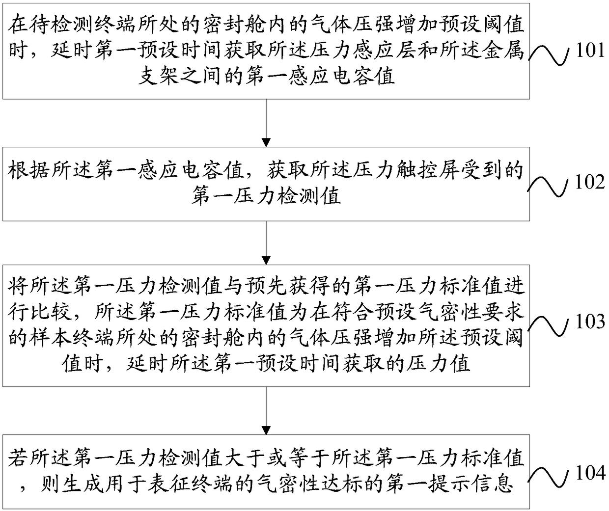
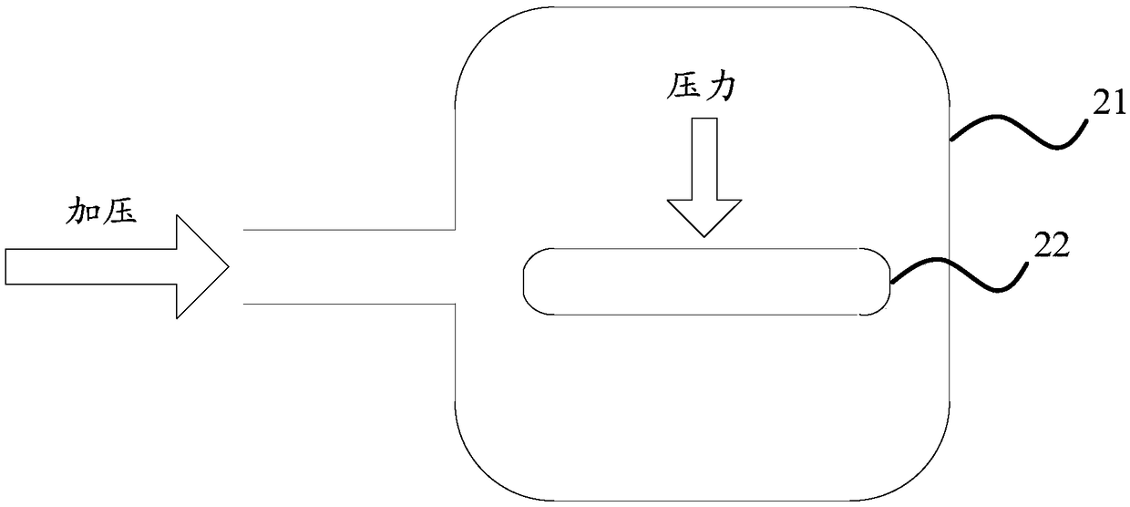
[0027] refer to figure 1 As shown, the air tightness detection method of the embodiment of the present invention includes:

[0028] Step 101, when the gas pressure in the airtight chamber where the terminal to be detected is located increases to a preset threshold, delaying for a first preset time to obtain a first sensing capacitance value between the pressure sensing layer and the metal bracket.

[0029] The method in the embodiment of the present invention is applied to a terminal with a pressure touch screen, and the terminal further includes a pressure sensing layer and a metal bracket sequentially disposed under the pressure touch screen. Specifically, in addition to the pressure touch screen, the terminal also includes an LCM (LCD Modul, liquid crystal display module), a pressure sensing layer, a metal bracket, a battery, and a rear cover arranged sequentially below the pressure touch screen, wherein There is a gap between the pressure sensing layer and the metal suppo...

no. 2 example

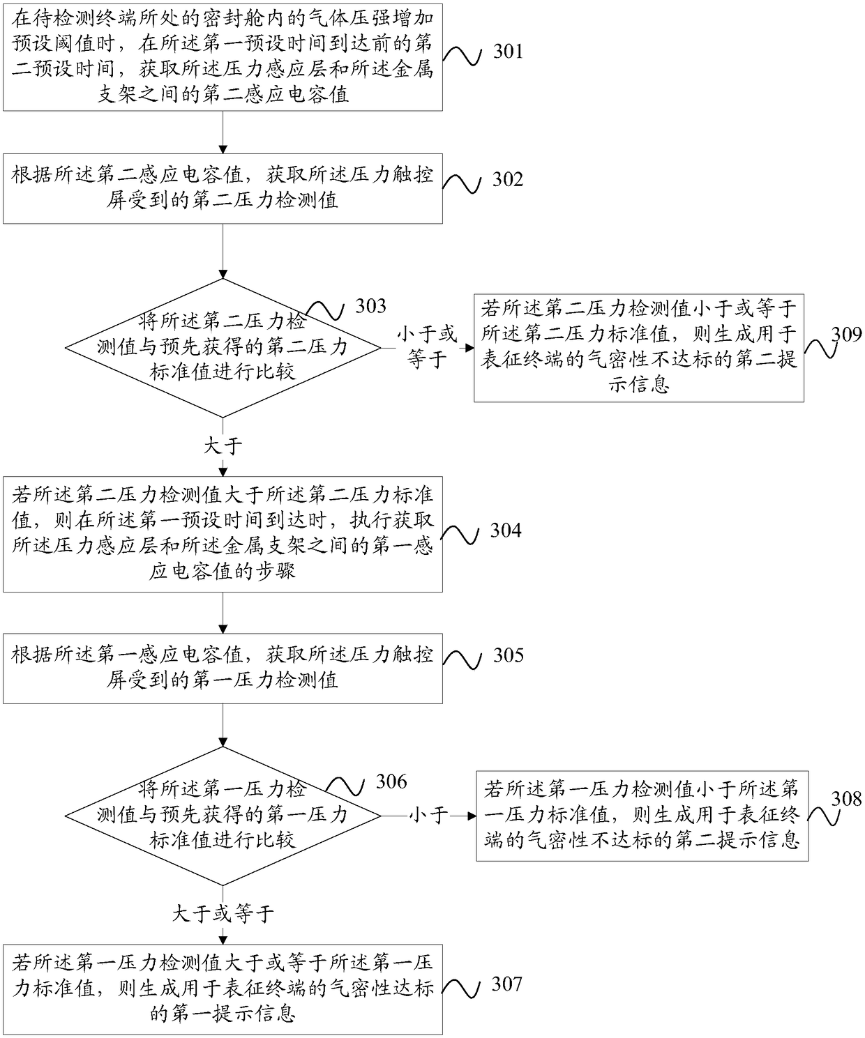
[0048] refer to image 3 As shown, the air tightness detection method of the embodiment of the present invention includes:

[0049] Step 301, when the gas pressure in the airtight cabin where the terminal to be detected is located increases to a preset threshold, acquire the pressure sensing layer and the metal bracket at a second preset time before the first preset time arrives. between the second sense capacitance value.

[0050] The method in the embodiment of the present invention is applied to a terminal with a pressure touch screen, and the terminal further includes a pressure sensing layer and a metal bracket sequentially disposed under the pressure touch screen. Specifically, in addition to the pressure touch screen, the terminal also includes an LCM (LCD Modul, liquid crystal display module), a pressure sensing layer, a metal bracket, a battery, and a rear cover arranged sequentially below the pressure touch screen, wherein There is a gap between the pressure sensin...


PUM


Abstract

The present invention provides an air tightness detection method and a mobile terminal and belongs to the electronic technical field. With the method adopted, the problems of low efficiency and high cost of existing terminal air tightness detection can be solved. The method comprises the following steps that: when the pressure intensity of a gas in a sealed cabin where a terminal is located is increased by a preset threshold value, first preset time is delayed, a first induced capacitance value between a pressure sensing layer and a metal support is obtained; a first pressure detection value borne by a pressure touch control screen is obtained; the first pressure detection value is compared with a first pressure standard value, wherein the first pressure standard value is a value which is obtained by increasing the pressure intensity of the gas in the sealed cabin where the sample terminal satisfying a preset air tightness requirement is located by the preset threshold value with the delay of the first preset time performed; and if the first pressure detection value is greater than or equal to the first pressure standard value, first prompting information characterizing that the air tightness of the terminal reaches standards is generated. With the air tightness detection method of the invention adopted, the air tightness of the terminal can be accurately detected, complicated and precise test equipment is not required, detection costs are reduced, and detection efficiency can be improved.

Description

technical field [0001] The present invention relates to the field of electronic technology, and more specifically, to an airtightness detection method and a mobile terminal. Background technique [0002] With the increasing development of communication and multimedia functions of smart terminals, they play an increasingly important role in users' lives. In order to adapt to harsh environments such as humidity, sweat, rain, and even immersion in water, the waterproof requirements for smart terminals are getting higher and higher. Waterproofing requires smart terminals to have a good structural airtightness to ensure that water cannot enter the inside of the smart terminal and avoid corrosion of electronic components that will cause mobile phone functions to fail. [0003] At present, in the production process of the existing technology, the airtightness of the waterproof smart terminal needs to be tested one by one to ensure the consistency of the product. However, it needs...

Claims


Application Information

Patent Timeline
Patent Type & Authority Patents(China)
IPC IPC(8): G01M3/26
CPCG01M3/26
Inventor 张涛
Owner VIVO MOBILE COMM CO LTD
Learn More