
A structured light illumination super-resolution microscopy imaging method

A technology of structured light illumination and microscopic imaging, which is applied in the direction of material analysis, material analysis, fluorescence/phosphorescence, etc. by optical means, which can solve the problems of small calculation amount, failure to provide iteration, sacrifice of speed and accuracy, etc.

Active Publication Date: 2019-07-19
PEKING UNIV
View PDF7 Cites 0 Cited by
  • Summary
  • Abstract
  • Description
  • Claims
  • Application Information

AI Technical Summary

Problems solved by technology

In addition, Heintzmann and Cremer proposed a four-phase reconstruction method, which has a small amount of calculation, but four original images need to be obtained for the illumination fringe in each direction, and the initial phase of the illumination fringe The requirements for value accuracy are high, so it is not commonly used [2]
There are new ways to reduce the number of images required for reconstruction down to 4 [3,4] , but these methods are based on iteration in the space domain rather than the frequency domain solution in the traditional method, which may produce more artifacts and fail to provide a theoretical explanation for the convergence of the iteration
And these methods of reducing the number of required images have higher requirements for the accuracy of structured light phase
From the perspective of system construction, when using a grating to generate lighting stripes, it is necessary to use a mechanical method to control the translation of the grating, resulting in the sacrifice of speed and accuracy.

Method used


Image

  • A structured light illumination super-resolution microscopy imaging method
  • A structured light illumination super-resolution microscopy imaging method
  • A structured light illumination super-resolution microscopy imaging method

Examples


Embodiment Construction

[0039] The present invention will be further elaborated below through specific embodiments in conjunction with the accompanying drawings.

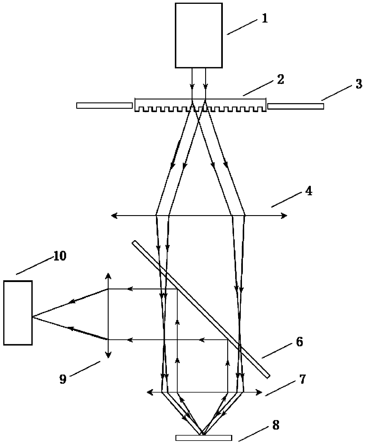
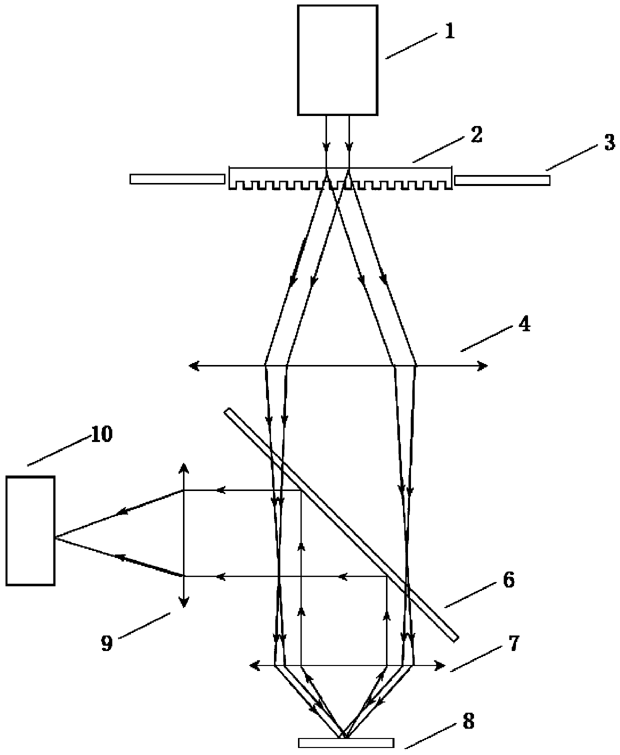
[0040] like figure 1 As shown, the structured light illumination super-resolution microscopy imaging system of this embodiment includes: an illumination light source 1, a rotating structured light generator 2, a rotating device 3, a first converging lens 4, a dichroic mirror 6, an objective lens 7, and an object Stage 8, sample, second converging lens 9 and digital imaging device 10; wherein, the rotating structured light generator 2 adopts a grating, is arranged on the rotating device 3, takes the optical axis as the rotating axis, and the rotating device drives the grating to rotate 360°, The rotation angle is not fixed; the illumination source 1 emits excitation light; the excitation light is diffracted by the grating; the diffracted excitation light is converged by the first converging lens 4, transmitted by the dichroic mirror 6, focu...


PUM


Abstract

The invention discloses a structure illumination super-resolution microscopy imaging system and an imaging method thereof. The imaging system comprises an illumination light source, a rotating structure light generator, a first convergent lens, a light splitter, an objective lens, an object stage, a sample, a second convergent lens, a digital imaging device and a computer. An original image is processed through an imaging image reconstruction algorithm; super-resolution can be achieved only by rotating structured light stripes for four times without phase displacement; the imaging image reconstruction algorithm is based on frequency domain processing instead of non-spatial domain processing; a spectrum process of a super-resolution image of a sample is different from a traditional frequency domain method, structured light directions are not analyzed one by one and all directions are merged for analysis; in order to obtain traditional uniform 2-fold resolution improvement in various directions, the theoretical quantity of original images can be reduced to 4 from 9 of a traditional method; the quantity of the original images is further reduced to 3 and uniform 1.5fold resolution improvement in various direction can be theoretically obtained.

Description

technical field [0001] The invention relates to optical microscopic imaging technology, in particular to a structured light illumination super-resolution microscopic imaging system and an imaging method thereof. Background technique [0002] Super-resolution optical microscopy utilizes spatial or temporal modulation of fluorescence emission to achieve microscopic imaging that breaks through the optical diffraction limit. Structure Illumination Microscopy (SIM), based on wide-field fluorescence microscopy, uses specially modulated structured light to illuminate the sample, uses specific algorithms to extract high-frequency information from the modulated image, and breaks through diffraction. The limit of the limit. [0003] Conventional reconstruction methods for 2D SIM require at least 9 original images. The reconstruction method proposed by Gustafsson [1] , take 3 different initial phases in each lighting direction value, obtain 3 original images, and obtain the high-f...

Claims


Application Information

Patent Timeline
Patent Type & Authority Patents(China)
IPC IPC(8): G01N21/64
CPCG01N21/6458
Inventor 阿密特·莱尔席鹏赵堃
Owner PEKING UNIV
Learn More