
Path planning method for agricultural plant protection drones avoiding obstacles and spraying drones

A technology for planting and protecting drones and drones, which is applied in vehicle position/route/altitude control, navigation, instruments and other directions to achieve the effect of reducing the area

Active Publication Date: 2019-11-22
NORTHEAST AGRICULTURAL UNIVERSITY
View PDF3 Cites 0 Cited by
  • Summary
  • Abstract
  • Description
  • Claims
  • Application Information

AI Technical Summary

Problems solved by technology

[0006] The purpose of the present invention is to solve the shortcoming that the obstacle avoidance algorithm in the prior art fails to take into account the shortcoming of reducing the length of the path and reducing the missed spraying of heavy spraying, and proposes a new obstacle avoidance path planning method for plant protection drones and unmanned aerial vehicles. man-machine

Method used

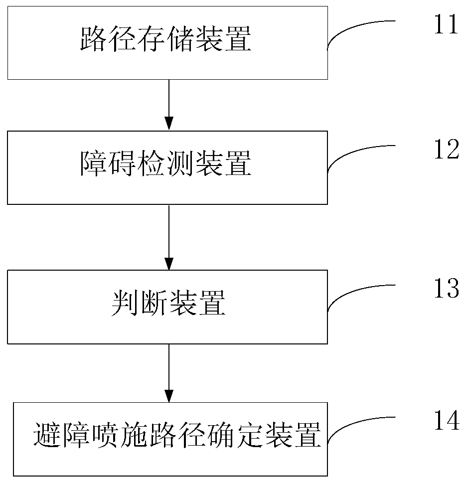

Image

  • Path planning method for agricultural plant protection drones avoiding obstacles and spraying drones
  • Path planning method for agricultural plant protection drones avoiding obstacles and spraying drones
  • Path planning method for agricultural plant protection drones avoiding obstacles and spraying drones

Examples


specific Embodiment approach 1

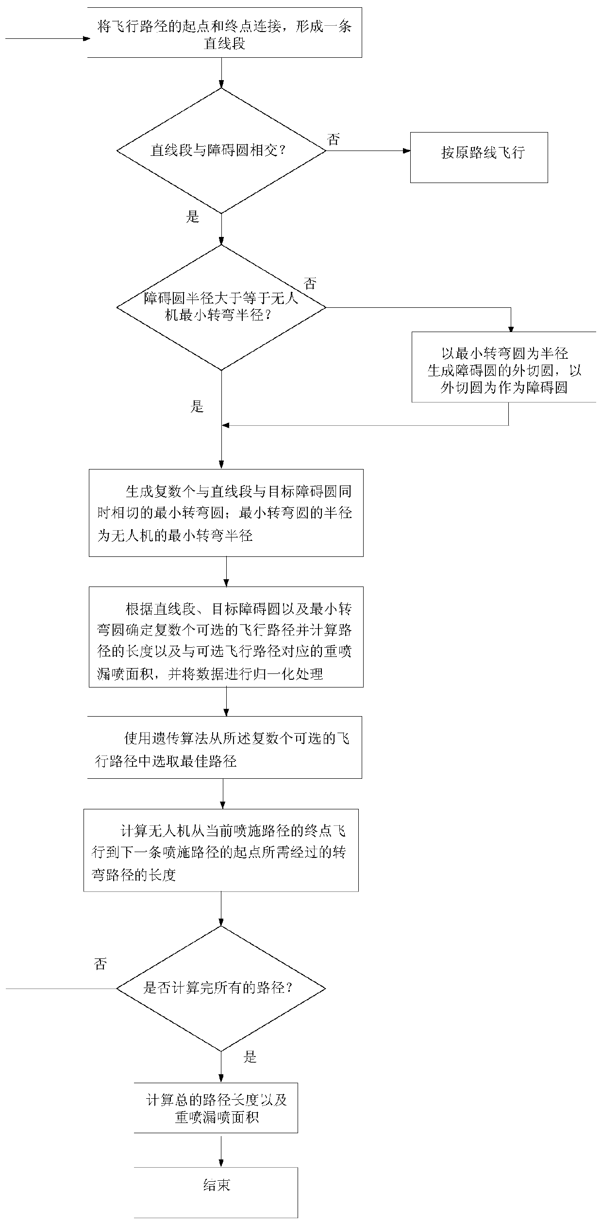
[0042] Specific embodiment 1: The obstacle avoidance path planning method for plant protection drones in this embodiment, the method is used to plan the flight path, the flight path includes at least one straight spraying path and at least one turning path, each straight spraying path Including a starting point and an end point, each turning path represents a path from the end point of a straight spraying path to the starting point of the next straight spraying path, characterized in that the method includes:

[0043] Step 1) From the first straight line spray path, the starting point and the end point of the current flight path are connected to form a straight line segment for representing the original flight path;

[0044] Step 2) Judging whether the straight line segment intersects with the obstacle circle, if it does not intersect, then fly straight along the original route, if it intersects, then perform step 3); the obstacle circle is a model used to represent the positio...

specific Embodiment approach 2

[0057] Specific implementation mode two: the difference between this implementation mode and specific implementation mode one is:

[0058] The length of the flight path of each optional path in step 5) is calculated by the following formula:

[0059]

[0060] Where N is the total number of obstacles that must be avoided on a single path, N 1 is the number of obstacle circles on the opposite side of the obstacle circle and the minimum turning circle, N 2 is the number of obstacle circles on the same side as the obstacle circle and the minimum turning circle, and satisfies N 1 +N 2 =N; where b is the length of the straight line; R z is the minimum turning radius of the UAV;

[0061] When the radius of the obstacle circle is greater than or equal to the minimum turning radius of the UAV, L d is the distance from the center of the obstacle circle to the straight line segment, R i is the radius of the obstacle circle;

[0062] When the radius of the obstacle circle is sma...

specific Embodiment approach 3

[0065] Specific embodiment three: the difference between this embodiment and specific embodiment one or two is:

[0066] Step 5) in each of the optional paths of the re-spray missed spray area is calculated by the following formula:

[0067]

[0068] Other steps and parameters are the same as those in Embodiment 1 or Embodiment 2.


PUM


Abstract

The invention provides an agricultural plant protection unmanned aerial vehicle and an obstacle avoidance and spraying path planning method for the same, and relates to the field of route planning methods and control methods for unmanned aerial vehicles. The agricultural plant protection unmanned aerial vehicle and the novel obstacle avoidance and spraying path planning method aim to overcome the shortcoming that reduction of the lengths of existing paths and reduction of repeated spraying and missed spraying cannot be taken into account by obstacle avoidance algorithms in the prior art. The obstacle avoidance and spraying path planning method includes judging whether straight line sections intersect with obstacle circles or not; generating Dubins paths if the straight line sections intersect with the obstacle circles, determining all optional flight paths and calculating flight path lengths of first paths, the lengths of swerving path, and repeated spraying areas; repeatedly carrying out previous steps until all flight path lengths and repeated spraying areas are calculated. The straight line sections comprise starting points and end points of first spraying paths. The agricultural plant protection unmanned aerial vehicle and the obstacle avoidance and spraying path planning method have the advantages that genetic algorithms are additionally implemented in order to quickly find out the optimal paths, and the optimal paths can be quickly selected from the optional flight path; the obstacle avoidance and spraying path planning method is applicable to plant protection unmanned aerial vehicles.

Description

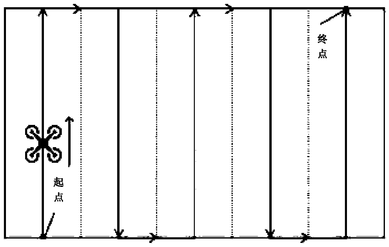
technical field [0001] The invention relates to an obstacle-avoiding spraying path planning method for an agricultural plant protection drone and the drone, and belongs to the field of the drone route planning method and control method. Background technique [0002] The area of ​​plant protection UAV spraying operation is generally large, and the UAV is small in size and flexible in response. Therefore, the general plant protection UAV spraying route is planned to be in the shape of "Π" back and forth. As shown in Figure 3, Figure 3(a) is a standard rectangular spraying area, and Figure 3(b) is an irregular spraying area, but their planned routes are all reciprocating. This back-and-forth route is especially good for the efficiency of the spraying operation and the uniformity of spraying (respray and miss spray) without obstacles. But in practical applications, this kind of unobstructed drone spraying operation hardly exists. Plant protection drones are likely to encounter...

Claims


Application Information

Patent Timeline
Patent Type & Authority Patents(China)
IPC IPC(8): G05D1/10G01C21/00
CPCG01C21/00G05D1/101
Inventor 张喜海范成国房俊龙孟繁锋许绥佳乔岳
Owner NORTHEAST AGRICULTURAL UNIVERSITY
Learn More