

Airline planning method and device for surveying and mapping unmanned aerial vehicle
A UAV and route technology, applied in the field of UAV surveying and mapping, can solve the problems of prone to errors, relatively large target area restrictions, waste of time, etc., to save time, shorten working time, and improve flexibility.
- Summary
- Abstract
- Description
- Claims
- Application Information
AI Technical Summary
Problems solved by technology
Method used
Image

Examples
Embodiment 1
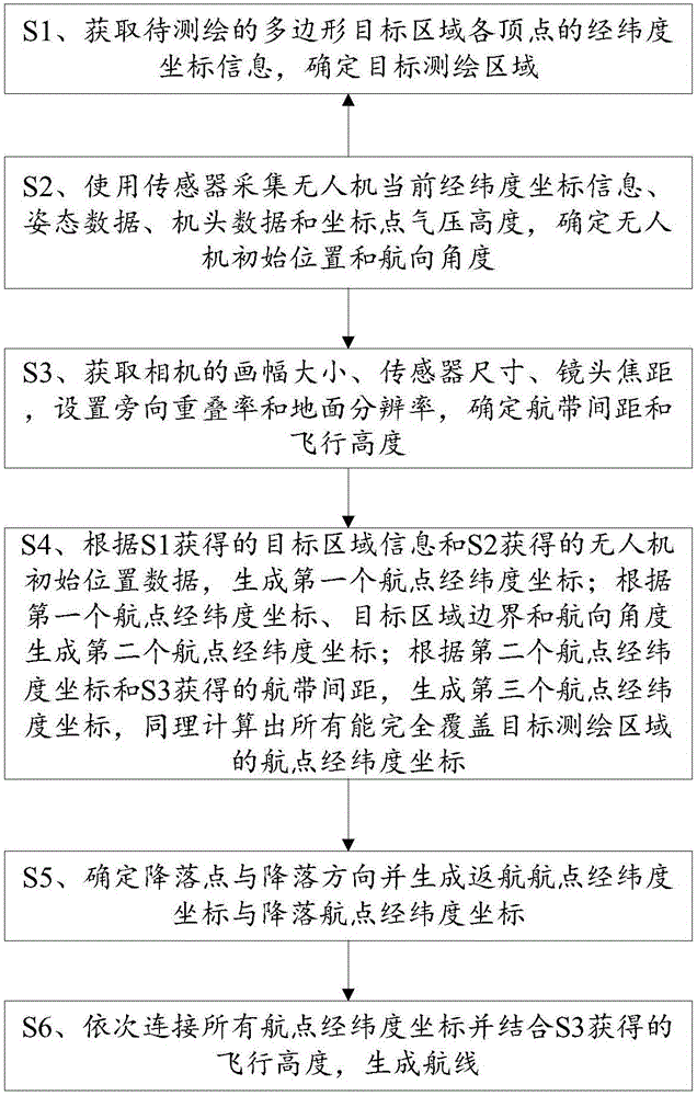
[0050] Please refer to figure 1 , Embodiment 1 of the present invention is: a method for route planning of a surveying and mapping unmanned aerial vehicle, specifically comprising the following steps:
[0051] S1. Input and obtain the latitude and longitude coordinate information of each vertex of the polygon target area to be surveyed and mapped, and determine the target surveyed and mapped area. The target area can be selected in real time on the map, and the selected area can be any polygon, which can fully describe the object being surveyed and mapped. Before determining the target surveying and mapping area, it is necessary to extend a certain distance outward according to the boundary of the original target area. The extended distance can be set according to the actual situation to ensure that the surveying and mapping drone can capture comprehensive target area information as much as possible during the mission. .
[0052] S2. Use the sensors on the UAV to collect the...
Embodiment 2
[0062] An embodiment of the present invention relates to a route planning device for a surveying and mapping UAV, which corresponds to the method in Embodiment 1, including:
[0063] The input terminal is used to obtain the coordinate information of the target area to be mapped;
[0064] The preprocessing module is used to perform an extension process on the coordinate information of the input target area;
[0065] The sensing module is used to sense the current state parameters and flight environment of the UAV;
[0066] The collection module is used to collect shooting parameters of the camera;
[0067] A computing module, configured to generate position information of each waypoint;
[0068] The return processing module is used to determine the position information of the return point and the landing point;
[0069] The route generation module is used to generate the final route.
[0070] The adjustment module, if the sensing module detects that the current flight envir...
PUM
 Abstract
Description
Claims
Application Information