
90-degree transfer button

A button and a part of the technology, applied in the field of mechanical and electronic equipment, can solve the problems of reducing the reliability of the whole machine, increasing the cost, and reducing the aesthetics of the equipment, and achieve the effect of wide application range, high reliability and simple structure

Inactive Publication Date: 2017-05-31
BEIJING INST OF RADIO MEASUREMENT
View PDF4 Cites 6 Cited by
  • Summary
  • Abstract
  • Description
  • Claims
  • Application Information

AI Technical Summary

Problems solved by technology

However, many electronic devices are packaged in the case at present, and the normal line of the operation panel of the case forms an angle of 90° with the switch of the electronic device. Generally, it is necessary to open a hole on the operation panel, and the hands are inserted into the case to operate, which will inevitably cause the device to be damaged. The aesthetics are reduced, and the chassis cannot achieve airtightness
If the operation panel is designed to have a quick opening / closing function, a large number of structural parts such as hinges, quick locks, and loose screws will be added, which will also increase the complexity of the equipment, increase the cost, and reduce the reliability of the whole machine

Method used


Image

  • 90-degree transfer button
  • 90-degree transfer button

Examples


Embodiment Construction

[0030] The principles and features of the present invention are described below in conjunction with the accompanying drawings, and the examples given are only used to explain the present invention, and are not intended to limit the scope of the present invention.

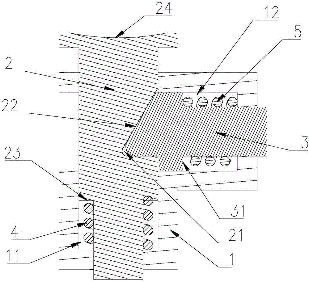
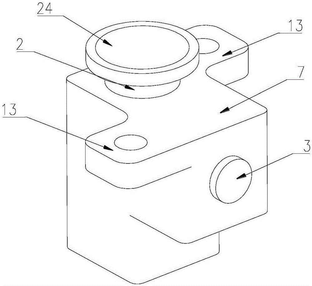
[0031] Such as figure 1 and figure 2 As shown, a 90° transfer button in this embodiment includes a housing 1, a button 2, and a slider 3. The housing 1 is provided with a first through hole 11 and a second through hole 12, and the first through hole 12 is opened on the housing 1. A through hole 11 and a second through hole 12 are arranged vertically and communicate with each other;

[0032] A part of the button 2 is inserted into the first through hole 11, and a first A spring 4; the button 2 is provided with a positioning engaging part corresponding to the position of the second through hole 12;

[0033] The slider 3 is passed through the second through hole 12, one end of the slider 3 fits and engages with the...


PUM


Abstract

The invention relates to a 90-degree transfer button, which comprises a shell, a button and a sliding block, wherein a first through hole and a second through hole are formed in the shell; the first through hole and the second through hole are vertically arranged and communicate with each other; one part of the button is inserted into the first through hole, wherein a first spring which is arranged along the axial direction of the first through hole is crimped between the part in the first through hole and the inner wall of the first through hole; the button is provided with a locating clamping part corresponding to the position of the second through hole; the sliding block is arranged in the second through hole in a penetrating manner, one end of the sliding block is adaptively clamped with the locating clamping part and the other end of the sliding block is located at the outer side of the second through hole; and a second spring which is arranged along the axial direction of the second through hole is crimped between the sliding block and the inner wall of the second through hole. According to the button provided by the invention, the sliding block can be driven to slide outside along the second through hole and to be propped against a switch of electronic equipment, so that on / off of the electronic equipment is achieved, any fastener is not needed and the 90-degree transfer button is high in reliability, wide in application range and low in cost.

Description

technical field [0001] The invention relates to the technical field of mechanical and electronic equipment, in particular to a 90° transfer button. Background technique [0002] The button is a common appliance in the current mechanical and electronic equipment, which realizes the rapid switching of the mechanical and electronic equipment. However, many electronic devices are packaged in the case at present, and the normal line of the operation panel of the case forms an angle of 90° with the switch of the electronic device. Generally, it is necessary to open a hole on the operation panel, and the hands are inserted into the case to operate, which will inevitably cause the device to be damaged. The aesthetic level of the computer is reduced, and the airtightness of the chassis cannot be achieved. If the operation panel is designed to have a quick opening / closing function, a large number of structural parts such as hinges, quick locks, and loose screws will be added, which w...

Claims


Application Information

Patent Timeline
Patent Type & Authority Applications(China)
IPC IPC(8): H01H13/04H01H13/14H01H13/28
CPCH01H13/04H01H13/14H01H13/28
Inventor 夏海豹
Owner BEIJING INST OF RADIO MEASUREMENT
Learn More