Intelligent electric-lamp type fishing float with improved structure

An electronic light and intelligent technology, applied in fishing accessories, fishing, applications, etc., can solve the problems of the floating body (large weight, inflexible rotation, reduced sensitivity, etc., to reduce the weight of the floating body and reduce the floating body) Volume, the effect of improving production efficiency

Inactive Publication Date: 2015-10-07
谭振黔
View PDF7 Cites 3 Cited by
  • Summary
  • Abstract
  • Description
  • Claims
  • Application Information

AI Technical Summary

Problems solved by technology

Therefore, in the design and production of smart light floats with this structure, the weight of the tension pendulum must be greater than a fixed value of 2 grams, and the volume of the tension pendulum must be greater than a fixed value. It needs to be greater than a fixed value, and the diameter of the float tube directly limits the further reduction of the volume and weight of the entire float, which makes the volume (weight) of the float of this structure too large, and it is not light, flexible and handy enough for fishing operations.
[0004] The tension pendulum is set inside the float tube, and the bottom cover of the float must be disassembled before the pull pendulum can be disassembled, and the tension pendulum hidden in the float tube is lagging behind due to pollutants and is not easy to clean.
[0005] The original tension pendu

Method used


Image

  • Intelligent electric-lamp type fishing float with improved structure
  • Intelligent electric-lamp type fishing float with improved structure
  • Intelligent electric-lamp type fishing float with improved structure

Examples


specific Embodiment approach

[0041] Specific embodiments: the present invention will be further described below in conjunction with accompanying drawings and specific examples

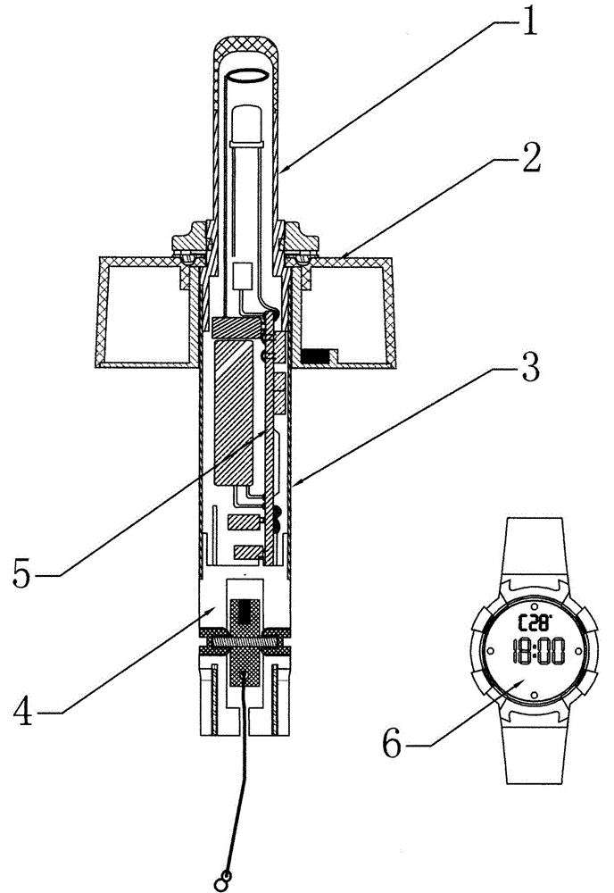
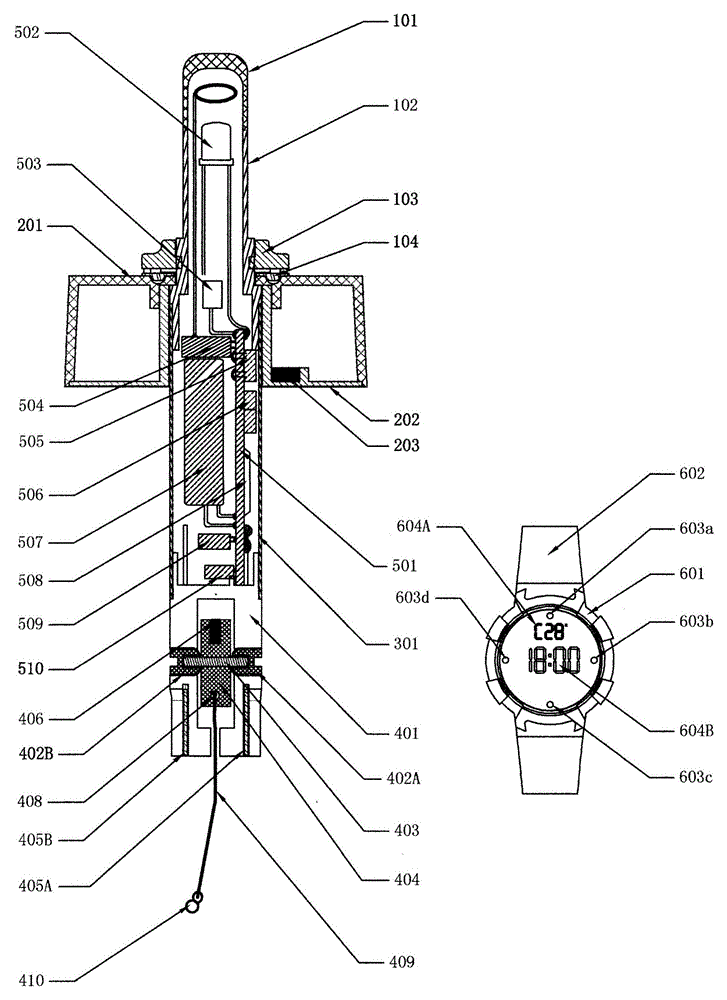
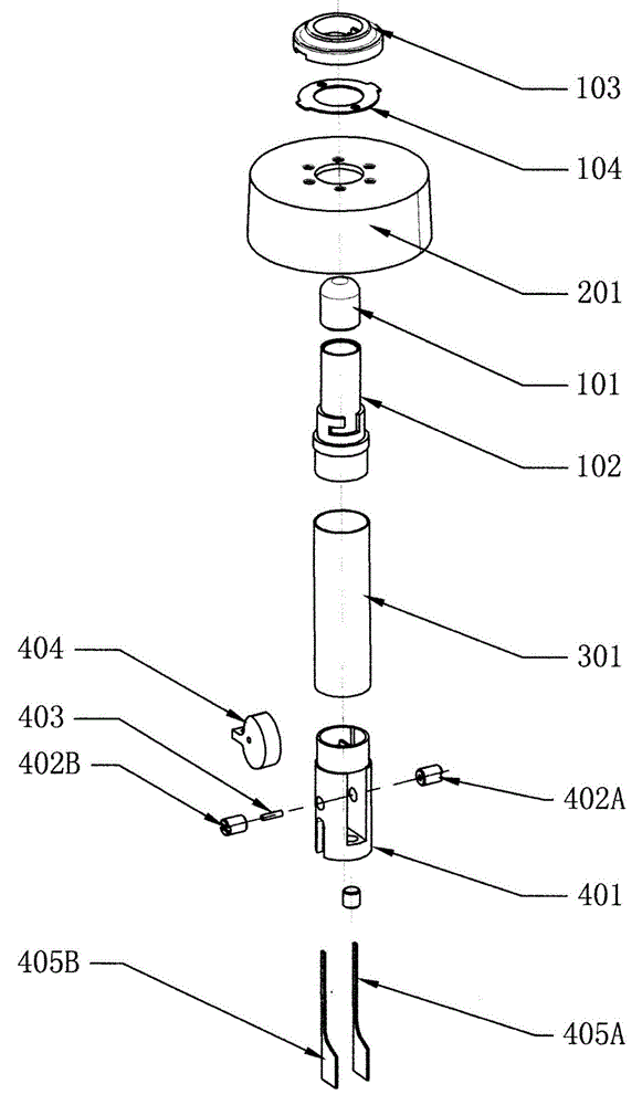
[0042] exist figure 1 and figure 2Among them, the device is composed of a float head 1, a float aid plate 2, a float body tube 3, a float base 4, a circuit board 5 and a fish news receiving device 6. Its specific structure is as follows: the upper end of the drift tube 301 is embedded with screw connection or glued to the lower end of the drift head tube 102, the lower end of the drift tube 301 is embedded with a screw connection or glued to the upper end of the drift base 401, and the upper end of the drift head tube 102 is embedded with a glue joint drift. The lower end of the top cap 101; the buoyancy aid plate 2 is sleeved on the outer bottom of the float head tube 102, and the collar 103 is inserted along the float head tube 102 to press the float aid plate 2, and then it can be rotated forward and buckled on the float head...


PUM


Abstract

The invention relates to further optimization and improvement on the structure and function of a fishing float on the basis of an invention patent invented by the inventor and named "all-weather multifunctional intelligent electric-lamp type fishing float" (201210029821.9). Key points of the improvement of the structure are that a tension pendulum is arranged outside a float body tube, so that the tension pendulum is not restricted by the diameter of the float body, and the size and weight of the float body can be reduced; the tension pendulum employs spherical axis positioning screws for installation, so that the production efficiency of products and the trigger sensitivity of the fishing float can be improved; a charging electrode employs an inverted flag-shaped electrode slice contact charging structure, so that the charging operation can be more convenient; floating assisted discs are made of plastic or light metal and form an independent cavity, so that the floating assisted discs and the float body can be dismounted into two parts and then can be hold in boxes respectively, and electric quantity loss due to error switching on/off is avoided; and a fish information receiving device is matchedly used, so that angling can be carried out in a mode of fish information emitting, signal receiving, and sound or voice prompting, and therefore the fishing float can be used all-weather.

Description

technical field [0001] The invention relates to an electronic "fishing float", which should be named "fishing float" to be precise, and in particular to an intelligent electronic lamp type fishing float whose structure has been optimized and improved. Background technique [0002] The electronic fishing floats currently sold in the market and recorded in patents are basically traditional wooden electronic fishing floats, induction electronic fishing floats and the multifunctional intelligent electronic lamp type fishing floats invented by me. In my invention patent (ZL201210029821.9) of "all-weather multifunctional intelligent electronic light fishing float", the intelligent electronic light fishing float breaks through the principle and structure of traditional wooden fishing floats or other electronic fishing floats, and provides An energy-saving and environmentally friendly type that can be triggered with high sensitivity, and can clearly identify the action rhythm of fis...

Claims


Application Information

Patent Timeline
IPC IPC(8): A01K93/02
Inventor 谭振黔
Owner 谭振黔
Why Eureka
Try Eureka