
Cover body structure of storage battery

A battery and cover technology, applied in the direction of batteries, structural parts, battery pack components, etc., can solve the problems of unreasonable structure, difficult liquid injection of batteries, unsatisfactory exhaust performance, etc., to optimize the use performance and optimize liquid injection. performance, the effect of optimizing exhaust performance

Pending Publication Date: 2017-05-31
ZHEJIANG CHANGXING KISUN POWER SUPPLY
View PDF5 Cites 1 Cited by
  • Summary
  • Abstract
  • Description
  • Claims
  • Application Information

AI Technical Summary

Problems solved by technology

[0004] The battery cover structure provided by the present invention aims to overcome the disadvantages of the unreasonable structure of the battery cover in the prior art, which cause difficulty in liquid injection and unsatisfactory exhaust performance of the battery

Method used


Image

  • Cover body structure of storage battery

Examples


Embodiment 1

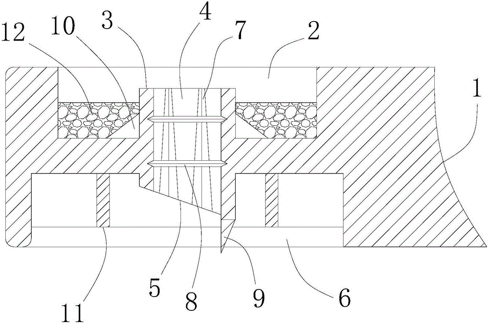
[0019] Such as figure 1 As shown, a battery cover structure includes a cover 1, a groove 2 is opened on the cover 1, a boss 3 is integrally provided in the groove 2, and the boss 3 penetrates the groove 2 The bottom wall of the bottom wall, and the boss 3 extends to both sides of the bottom wall of the groove 2, the cover 1 is also provided with a groove body 6, and the end of the boss 3 away from the groove 2 is located in the groove body 6 Inside, the material between the groove 2 and the groove body 6 forms the bottom wall of the groove 2, that is, the groove 2 and the groove body 6 share a piece of material, and the boss 3 extends to both sides of the bottom wall of the groove 2 means, The boss 3 protrudes to both sides of the common material, that is, a part of the boss 3 is located in the groove 2, and the other part of the boss 3 is located in the groove body 6, and the boss 3 and the cover body 1 are formed by a mold;

[0020] Such as figure 1 As shown, the boss 3 is...

Embodiment 2

[0027] This embodiment is a further optimization of the first embodiment, so that the cover body 1 has better performance. Such as figure 1 As shown, the lower end of the boss 3 is provided with a guide rib 9 extending along the axial direction of the boss 3 at the lowest position of the inclined opening 5, and the side wall of the guide rib 9 is parallel to the side wall of the liquid injection hole 4. together. The diversion ribs 9 and the cover body 1 are of an integrated structure, and the arrangement of the diversion ribs 9 facilitates the liquid entering the battery.

[0028] Such as figure 1 As shown, a reinforcing rib 10 is integrated between the boss 3 and the bottom wall of the groove 2 . The arrangement of the ribs 10 improves the strength of the cover body 1 , thereby prolonging the service life of the cover body 1 .

[0029] Such as figure 1 As shown, ribs 11 are integrally provided in the tank body 6 , and the ribs 11 are arranged in the tank body 6 in a gri...


PUM


Abstract

The invention relates to a cover body structure of a storage battery, and solves the problems of difficult liquid injection in the storage battery and low exhaust performance caused by the fact that a cover body structure of the storage battery in the prior art is unreasonable. According to the cover body structure of the storage battery provided by the invention, a groove is formed in a cover body, a boss is arranged on the bottom wall of the groove, a liquid injection hole is formed in the boss, a groove body is further formed in the cover body, an inclined opening is formed in the part, positioned inside the groove body, of the boss, an exhaust groove is formed in the side wall of the liquid injection hole, the cross section of the exhaust groove is V-shaped, and the width of the upper end of the exhaust groove is smaller than that of the lower end of the exhaust groove; compared with the prior art, liquid easily enters into the interior of the storage battery due to the existence of the inclined opening and the exhaust groove in the liquid injection process, so that the liquid injection performance of the storage battery is greatly optimized, gas inside the storage battery can be exhausted conveniently by using the exhaust groove in the liquid injection process, and the liquid injection operation of the storage battery is facilitated.

Description

technical field [0001] The invention relates to battery accessories, in particular to a battery cover structure. Background technique [0002] A battery is a device that provides electrical energy and is widely used in various fields. The storage battery generally includes a casing and a cover fixed on the casing. An electrode plate is arranged inside the casing, and the casing is also filled with electrolyte. The cover body plays a role of sealing the casing and preventing electrolyte leakage. In actual use, liquid may need to be added to the battery, and the characteristics of the battery itself make the battery need to be exhausted during discharging or charging. Therefore, the cover body of the battery is not completely sealed, and it should be possible to realize liquid injection and exhaust operation. [0003] The structure of the battery cover in the prior art is unreasonable, which makes it difficult to inject liquid into the battery during the liquid injection pr...

Claims


Application Information

Patent Timeline
IPC IPC(8): H01M2/04H01M2/12H01M2/36
CPCH01M2200/00H01M50/148H01M50/35H01M50/668Y02E60/10
Inventor 杨繁科开明敏许国强
Owner ZHEJIANG CHANGXING KISUN POWER SUPPLY
Learn More