Battery heat management system for electric vehicle with plate type heat pipe

A technology of battery thermal management and plate heat pipes, applied in secondary batteries, circuits, electrical components, etc., can solve problems such as shortening charging time and increasing energy density, avoiding complexity and potential safety hazards, reducing maximum temperature, and improving consistency sexual effect

Pending Publication Date: 2017-05-31
江乐新
View PDF6 Cites 15 Cited by
  • Summary
  • Abstract
  • Description
  • Claims
  • Application Information

AI Technical Summary

Problems solved by technology

However, while increasing the energy density and shortening the charging time, the battery will also emit more heat. How to quickly dissipat

Method used


Image

  • Battery heat management system for electric vehicle with plate type heat pipe
  • Battery heat management system for electric vehicle with plate type heat pipe
  • Battery heat management system for electric vehicle with plate type heat pipe

Examples


Embodiment 1

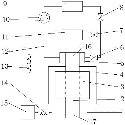
[0040]Embodiment 1: As shown in Figure 1, the electric vehicle battery thermal management system with plate heat pipes consists of a battery pack, a cooling system, a heating system and a control module 15. The battery pack is composed of a plurality of battery cells 3 , plate heat pipes 2 inserted between the battery cells 3 and a frame 4 . In this embodiment, the plate heat pipe 2 is a flat plate structure placed vertically. One end of the plate heat pipe along the length direction is a cooling end 16, and the other end is a heating end 17. The cooling end 16 of the plate heat pipe 2 is attached to the cooling plate 5 in the cooling system, and the heating end 17 is attached to the heating element 1 in the heating system. The middle part is attached to the battery cell 3 . There are multiple passages in the plate heat pipe 2, which are sealed by vacuuming, and the passages are filled with a working medium for phase change heat transfer. The cooling system is composed of an...

Embodiment 2

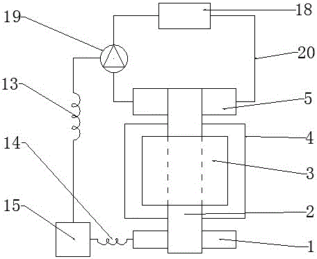
[0041] Example 2: If figure 2 As shown, in this embodiment, the cooling system is composed of a cooling plate 5 , a liquid pipeline 20 , a cooling module 18 and a water pump 19 . The heat dissipation module 18 is composed of a radiator and a fan, or is composed of a cooling device. This is a liquid-cooling system that also shares the same liquid-cooling system that the car uses to cool the engine. Other structures and working principles of this embodiment are the same as those of Embodiment 1.

Embodiment 3

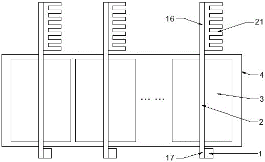
[0042] Example 3: image 3 It is a schematic diagram of the thermal conduction structure of the electric vehicle battery thermal management system with a plate heat pipe according to the present invention. The battery pack is composed of a plurality of battery cells 3, and the shape of the battery cells 3 is a cuboid. The plate heat pipe 2 is inserted between the electric cores 3, and its shape is L-shaped. The bottom edge of the L shape is the heating end 17, which is attached to the heating element 1, and the cooling plate 5 is attached to the cooling end 16 of the plate heat pipe 2. The entire battery pack is connected as a whole through the frame 4 . Other structures and working principles of this embodiment are the same as those of Embodiment 1.


PUM


Abstract

The invention relates to a battery heat management system for an electric vehicle with a plate type heat pipe. The system is composed of a battery pack, a cooling system, a heating system and a control module, wherein the plate type heat pipe is used as a key heat-conducting element of the battery; the battery pack is composed of a plurality of battery cells and the plate type heat pipe inserted among the battery cells; one end of the plate type heat pipe is attached to a cooling plate in the cooling system, the other end of the plate type heat pipe is attached to a heating element in the heating system, and a middle part of the plate type heat pipe is attached to the battery cells. The battery heat management system for the electric vehicle with the plate type heat pipe can rapidly educe and dissipate heat generated when a battery works, can also heat the battery when necessary, can maintain a temperature of the battery pack within a reasonable range, significantly improves consistency of a battery pack temperature field, can reduce weight of the battery pack, is simple in structure, safe and reliable, and is an efficient, practical and low-cost novel battery heat management system.

Description

technical field [0001] The invention relates to the field of electric vehicle battery thermal management, in particular to an electric vehicle battery thermal management system with a plate heat pipe. Background technique [0002] In recent years, with the development of electric vehicles, the performance requirements for electric vehicle batteries have become higher and higher. High energy density and fast charging are all higher requirements for electric vehicle batteries in the market. However, while increasing the energy density and shortening the charging time, the battery will also emit more heat. How to quickly dissipate the heat from the battery without increasing the volume and weight of the battery pack has always been a difficult problem in the industry. . In addition, when the temperature is low in winter, it is required to maintain the temperature of the battery above a certain temperature. How to control the battery pack within a certain temperature range in ...

Claims


Application Information

Patent Timeline
IPC IPC(8): H01M10/613H01M10/615H01M10/617H01M10/625H01M10/6552H01M10/6555
CPCH01M10/613H01M10/615H01M10/617H01M10/625H01M10/6552H01M10/6555Y02E60/10
Inventor 江乐新
Owner 江乐新
Why Eureka
Try Eureka